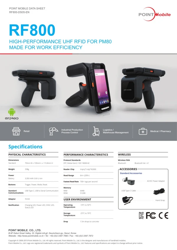
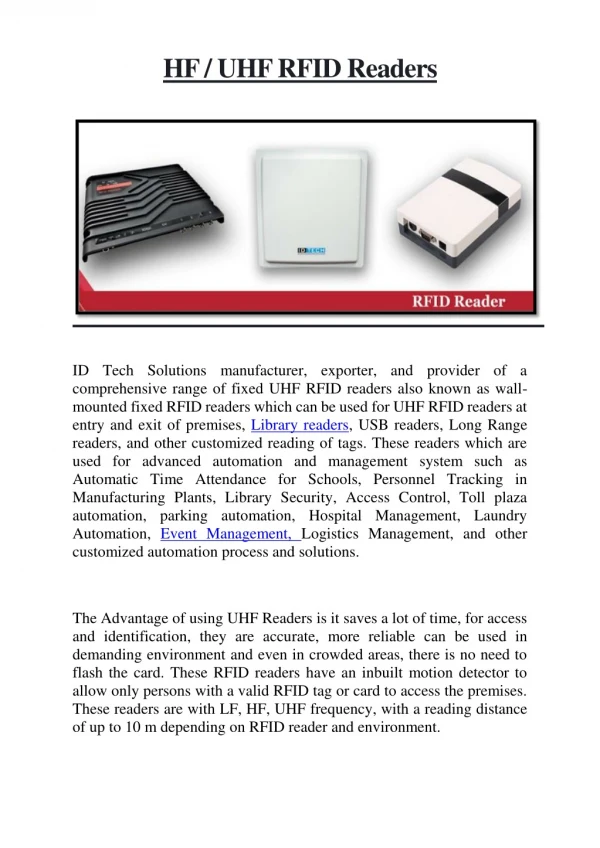
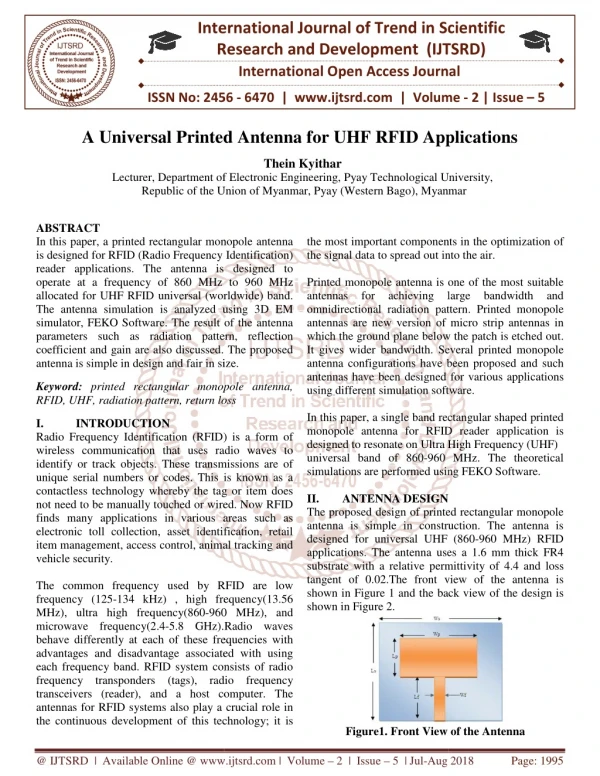
Download
1 / 29
310 likes | 464 Views
Chapter 19 - Simulators and Emulators for Different Abstraction Layers of UHF RFID Systems. Figure 19.1 Abstract overview of simulation/emulation cases. Figure 19.2 Tag Classes: UHF RFID Tags. Figure 19.3 Test Components. (a) Conformance Test Components. (b) Interoperability Test Components.

E N D
Chapter 19 - Simulators and Emulators for Different Abstraction Layers of UHF RFID Systems
Figure 19.3 Test Components (a) Conformance Test Components (b) Interoperability Test Components
Figure 19.4 System level design flow based on the methodology proposed
Figure 19.5 Components of implementation of the proposed methodology (a) Simulation platform (b) Real-time verification platform
Figure 19.6 Layers of a framework for UHF RFID system modeling
Figure 19.7 Hardware layer structure of the framework for UHF RFID system modeling
Figure 19.8 Structure of the software layer for UHF RFID system modeling
Figure 19.12 Simulation Platform for Multi-layer optimization
Figure 19.13 RF to baseband modeling approach (a) Carrier and baseband signals separation in the model - splitting in two components: (i) envelope and (ii) carrier frequency and phase (b) Separation of frequency and time domain analyses
Figure 19.15 Pre-computing and considering power off times (a) Pre-computing of Application-layer specifications for system simulation
Figure 19.15 Pre-computing and considering power off times (b) Gated data and clock signals represent tag inputs considering power-off times in time-discrete models
Figure 19.16 Cosimulation of the model with physical devices.
Figure 19.20 Structure of a higher class (active) UHF RFID tag
Figure 19.21 Mapping of the functional blocks on the tag hardware units
Figure 19.23 Lifetime Simulation of higher class tags a) Two level simulation set up
Figure 19.23 Lifetime Simulation of higher class tags (b) System level simulation - simulation principle
Figure 19.24 Logistics - container transport (b) Container tracking simulation results for two wake-up cycles: 4.8 s (a) and 2.8 s (b) - DPM: dynamic power management, EHD: energy harvesting device (a) Container surveillance simulation environment setup