Download
1 / 1

E N D
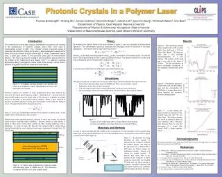
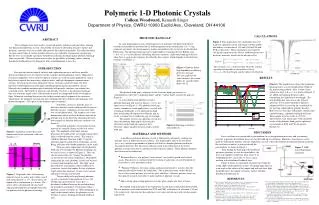
ABSTRACT New techniques have been used to create high quality multilayer polymer films, forming one-dimensional photonic crystals. The periodic structure of alternating refractive indices and dielectric constants were successfully fabricated by three different methods. The reflection band for spin-coated films of various numbers of layers was studied by transmission spectroscopy. Results were in reasonable agreement with theory indicating that high quality photonic band gap films are possible. We have begun to investigate the possibility of forming surface emitting distributed feedback lasers by doping the films with Rhodamine 6 laser dye. MATERIALS AND METHODS • A multilayer polymeric photonic crystal is fabricated by alternately stacking two polymer layers of different refractive indices. The higher index ratio of the two layers • (nhigh / nlow) and the larger number of periods will lead to a broader photonic band in the transmitted spectrum. For this reason, polymers used in the fabrication of the tested photonic crystals were chosen carefully for their refractive indices. Three different methods have been used for fabrication. Polymeric 1-D Photonic Crystals Colleen Woodward, Kenneth Singer Department of Physics, CWRU 10900 Euclid Ave., Cleveland, OH 44106 CALCULATIONS PHOTONIC BAND GAP Figure 5: This graph shows the calculations that were made for a photonic crystal with equal (100nm) widths and indices of refraction of 1.50 and 1.68 for PVA and PVK, respectively. These calculations were made by solving the equation for the electric field through the two dielectric materials, which, for the nth unit cell is: In a one-dimensional system, alternating layers of materials with different dielectric constants are periodic in one direction (z) and homogenous in the normal plane (xy). Using symmetry arguments, the electromagnetic modes sustainable by the crystal can be described in Bloch form. The photonic band gap can be understood by examining the first Brillion zone ( - π /a < kz≤π/a ) for different alternating dielectric constants. A photonic band gap will arise when there is a gap in the frequency described by these modes, which depends on the dielectric constants (see Figure 3). E(x) = The constants a, b, c, and d are then solved by a matrix equation that depends on the number of layers (Λ = a + b ), the wavelength, and the indices of refraction. Figure 3: Photonic Band Gap dependant on differing dielectric constants. The first graph has the same constants, the second differs by 1 and the third differs by 12. INTRODUCTION Research on ultra-fast optical switches and exploration into new and faster possible optical switching devices are of interest to the scientific and technological society. High-speed electrical components such as ultra-fast optical switches are useful in many applications such as high-density optical data processing, adaptive optics, and high-throughput communications systems. Presently, in electronic integrated circuits, electrons control electrons, but these materials would depend instead on light controlling light in microscale photonic circuits. Materials that combine nonlinear optical materials with periodic structures can enhance this switching action. The benefit of materials with periodic structures is the photonic band gaps that arise when the length scales of the periodic material are comparable to the wavelength of light. Enhanced switching then occurs due to the resonant optical response of the structures, which allows for nonlinear transmission and switching from the real (Kerr) and imaginary (two photon absorption – TPA) parts of the nonlinear optical response. RESULTS Figure 6: This graph clearly shows that a photonic band gap arises at a wavelength about 600nm by the spin-coating method. Also, as more layers (where one layer is d = a + b as shown in Figure 2) are added, the band gap becomes taller, transmitting less light of that wavelength. The only problem that arose was in the 32-layer spectrum. It was later found that a different solution of PVA was used for the second half of the layering, which did not properly dissolve. However, it is clear that, with proper solutions and careful layering, a photonic band gap will arise. These graphs were the result of a UV-Vis Spectrometer scan, which agree with calculated results of the photonic band gap for a photonic crystal made of PVK and PVA of specific thicknesses. The photonic band gap is analogous to the electronic band gap structure of semiconductors where the “conduction band” and the “valence band” separate the gap (see Figure 4). In a one-dimensional photonic crystal, a photonic band gap will occur so long as є1 / є2 is not equal to one (see Figure 3). The photonic band gap creates a number of useful applications; a crystal with a band gap could make a very good narrow-band filter by rejecting all frequencies within the gap, or create a resonant cavity within the gap, for example. The number of layers in a photonic crystal also affect the photonic band gap by increasing the reflectance in the band gap region per layer. Therefore, higher numbers of layers lead to a better band gap. A photonic crystal is a periodic array of dielectric materials which could possibly be used in photonic circuits. A photonic crystal can be three, two, or one dimensional. The simplest case is one-dimensional, where stacks of dielectric material are periodic only in one direction, alternating between two materials of different dielectric constants (see Figure 1). The period and indices of refraction of each material are carefully chosen to reflect or refract light. The amplitude of the index contrast determines the width of the wavelength region where light is reflected from the crystal. This region is called the photonic band gap width. Using the reflection and refraction effects of photonic crystals, Bragg reflectors with tunable properties can be There are many applications for the photonic band gap. For example, the photonic band gap can be used as lasers, as shown in Figure 2. They can also be used as filters by “tuning” the photonic crystal to filter out certain frequencies. By properly engineering the array, photonic crystals can be used to control and manipulate light. This light can be directed down certain paths, which could lead to even faster circuits that employ the use of photons (light) rather than electrons. In turn, faster circuits and optical switches can be made. The possibility of lasing through photonic crystals is currently being explored at Case. By introducing a gain material, a laser dye, a distributed-feedback laser can be created utilizing the periodicity and indices of refraction within a photonic crystal (see Figure 2). When pumping at an angle to the normal surface, the photonic crystal becomes a surface-emitting distributed-feedback laser. Figure 4: Band gap created in a semiconductor. Figure 1: A photonic crystal that is one-dimensional in the z-direction, with total thickness “a.” DISCUSSION Laser oscillators are created with a gain medium (to create population inversion) and a resonating structure to provide the feedback necessary for the build-up of oscillation. Mirrorless laser devices can be made by utilizing the periodic structure of photonic crystals, where the feedback mechanism (Bragg scattering due to refractive indices) is integrated with the gain medium, as shown in Figure 2. made. Figure 7: DFB Laser Experiment Schematic After finding the band gap of the produced polymeric photonic crystals described above, the next step would be to dope one layer with 1% wt of Rhodamine 6G, a laser dye, to use as a gain medium in the distributed feedback laser. Figure 6 shows an experiment schematic for testing the lasing ability of the photonic crystals. The pump light shines in at an angle to the surface of the sample and will emit laser light perpendicular to the sample, creating a surface-emitting distributed feedback laser. • Extrusion Process: two polymer “melt streams” are stacked, spread, and stacked again. This process is continued until the creation of a photonic crystal of hundreds of layers that is a few micrometers thick. • “Floating” Polymers: first spin-coating a polymer that dissolves in water, then the polymer that will be used in the fabrication. This is placed in water so that the thin layer of the second polymer rises off the glass and floats. Alternate polymer layers are then placed on top of each other to make multilayer photonic crystals. • Spin-coating: spin-coating polymers onto one glass sample, one layer at a time Figure 2: 1D periodic array of alternating dielectric layers n1 and n2 with widths a and b with total period d = a + b. The n2 layers are doped with a gain medium g as shown. The arrows show schematically the increased optical path length due to multiple reflections for photons near the photonic band edge. REFERENCES [8] Eric Baer, Anne P. Hiltner, Malcolm E. Kenney, Stuart J. Rowan, Kenneth D. Singer, Christoph Weder, “Nonlinear Photonic Crystals,” ONR BAA 05-017. [9] Michael J. Wiggins, Steven R. Flom, James S. Shirk, Richard G. S. Pong, Richard S. Lepkowicz, Aditya Ranade, Huiwin Tai, Eric Baer, Anne Hiltner, “Processing and Characterization of Nonlinear 1D Photonic Crystal Polymers.” Abstracts of Papers of the American Chemical Society 228: U502-U502 475-PMSE Part 2, Aug 22, 2004. [10]H. Kogelnik and C.V. Shank, “Stimulated Emission in a Periodic Structure.” Appl Physics Letters, 18 (4). 23 November 1970. [11]Jonathan P. Dowling, Michael Scalora, Mark J. Bloemer, and Charles M. Bowden, “The photonic band edge laser: A new approach to gain enhancement.” J. Appl. Phys. 75 (4), 15 February 1994. [12]A.E. Vasedekis, G.A. Turnbull, and I.D.W. Samuel, “Low Threshold edge emitting polymer distributed feedback laser based on a square lattice.” Appl. Phy. Letters 86, 161102. 11 April 2005. [1] Eric Baer, Anne P. Hiltner, Malcolm E. Kenney, Stuart J. Rowan, Kenneth D. Singer, Christoph Weder, “Nonlinear Photonic Crystals,” ONR BAA 05-017. [2] R.E. Slusher, B. J. Eggleton, “Nonlinear Photonic Crystals” [3] Amnon Yariv, Yeh Pochi, “Optical Waves in Crystals”, Ch. 6, “Electromagnetic Propagation in Periodic Media.” New York: Wiley, 1983. [4] John D Joannopoulos, Robert D. Meade, Joshua N. Winn, “Photonic Crystals: Molding the Flow of Light” [5] Charles Kittel, “Introduction to Solid State Physics,” 6th ed. John Wiley & Sons, Inc. New York, 1986. [6] Pochi Yeh, “Optical Waves in Layered Media.” Wiley, John & Sons, Inc. 2005. [7] Toshiyuki Komikado, Azusa Inoue, Koichi Masuda, Takashi Ando, Shinsuke Umegaki, “A Surface-Emitting Distributed-Feedback Laser from a Dye-Doped Polymeric Multi-Layer Fabricated by Spin Coating” The method used in this part of the experiment was the spin-coating fabrication method.The two polymers used in this method were PVA and PVK, with indices of refraction 1.50 and 1.68, respectively. Solvents for these polymers were water and toluene (with cyclohexanone), respectively.