Download
1 / 71
720 likes | 992 Views
Ch. 6 Digital Arithmetic and Arithmetic Circuits. 이 상 훈 경남대학교 전기전자공학부. 단원목차. 6.1 Digital Arithmetic 6.2 Signed Binary Numbers 6.3 Signed Binary Arithmetic 6.4 Hexadecimal Arithmetic 6.5 Numeric and Alphanumeric Codes 6.6 Binary Adders and Subtractors 6.7 BCD Adders

E N D
Ch. 6 Digital Arithmetic and Arithmetic Circuits 이 상 훈 경남대학교 전기전자공학부
단원목차 6.1 Digital Arithmetic 6.2 Signed Binary Numbers 6.3 Signed Binary Arithmetic 6.4 Hexadecimal Arithmetic 6.5 Numeric and Alphanumeric Codes 6.6 Binary Adders and Subtractors 6.7 BCD Adders 6.8 Carry Generation in MAX+PLUS II
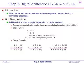
Basic Digital Arithmetic • Signed Binary Number: A binary number of fixed length whose sign (+/-) is represented by one bit (usually MSB) and its magnitude by the remaining bits • Unsigned Binary Number: A binary number of fixed length whose sign is not specified by a bit. All bits are magnitude and the sign is assumed +.
Unsigned Binary Arithmetic • Sum: Result of an Addition Operation of two (or more) binary numbers (operands). • Carry: A digit (or bit) that is carried over to the next most significant bit during an N Bit addition operation. • The carry bit is a 1 if the result was too large to be expressed in N bits.
Basic Rules (Unsigned) • One Bit Unsigned Addition 0 + 0 = 0 0 1 + 0 = 0 1 1 + 1 = 1 0 1 + 1 + 1 = 1 1 CIN A B COUT SUM
Binary Addition Examples • Binary Addition 1 Carry to next 1 1 1 1 1 1 0 0 1 0 1 0 1 0 1 1 1 0 + 1 0 1 0 1 0 0 1 0 0 1 1 0 1 1 1 0 0 1 0 1 0 0 0 0 0 1 Carry Out Bit
Basic Subtraction • Basic Subtraction of X = A - B with A= Minuend, B= Subtrahend and X = Difference or result. • Requires a Borrow Bit if A < B. • There are other forms of subtraction such as 2s Complement Addition used by Microprocessors (such as in a PC).
Basic Subtraction Rules • Binary 1 Bit Subtraction 0 - 0 = 0 0 1 - 0 = 0 1 1 - 1 = 0 0 10 - 1 = 0 1 BORROWIN A B
Binary Subtraction Examples • Binary Subtraction with Borrows () 1110 110(10) Borrow Stage -1001 100 1 010 1 10000 0111(10) Borrow ripples to LSB - 101 10 1 0101 1
Signed Binary Numbers I • Sign Bit: A bit (usually the MSB) that indicates whether a number is positive(=0) or negative (=1). • Magnitude Bits: The bits of a signed binary number that tell how large it is in value. • True Magnitude Form: A form of signed binary whose magnitude bits are the TRUE binary form (not complements).
Signed Binary Numbers II • 1s Complement: A form of signed binary in which negative numbers are created by complementing all bits. • 2s Complement: A form of signed binary in which the negative numbers are created by complementing all the bits and adding a 1 (1s Complement +1).
True Magnitude Form • 5 Bit Numbers Negative = S=1 +25 = 011001 Note sign bit = MSB = S = 0 -25 = 111001 Same as +25 with S=1 -12 = 101100 +12 = 001100 True magnitude
1s Complement Form • 8 Bit 1s Complement (Negative = S = 1) 57 = 0011 1001 -57 = 1100 0110 All Bits Inverted 72 = 0100 1000 -72 = 1011 0111
2s Complement Form • Used in MPU (PC) Arithmetic 57 = 0011 1001 -57 = 1100 0110 + 1 1011 1000 -72 = 1011 0111 + 1 1011 1000
Signed Binary Addition (8 Bit) • Signed Addition Positive S = 0 +30 = 0001 1110 +75 = 0100 1011 +105= 0110 1001 Similar to Binary addition with a Sign bit
Subtraction with 1s Complement • Add the 1s Complement and then Carry +80 = 0101 0000 (+80) = 0101 0000 -65 => 0100 0001 (+65) = 1011 1110 (1s Comp 65) 10000 1110 + 1(end-around carry) 0000 1111 (+15) Uses an End around carry addition method
2s Complement Subtraction • Add 2s Complement to Minuend +80 = 0101 0000 0101 0000 +65 = 0100 0001 +1011 1111 -65 = 1011 1110 +1 1 0000 1111 Discard Carry Bit from result
Negative Results • If the True Magnitude Form is used for subtraction the results are incorrect. (refer to p228) • If the result is from 1s or 2s Complement and the result is negative (S=1) the magnitude is found by taking the complement of the result.
Negative Result Example • 2s Complement Negative Result (65-80) +65 = 0100 0001 0100 0001 -80 = 1011 0000 (2s C.) +1011 0000 1111 0001 Invert 0000 1110 Add 1 + 1 Final Result = -15 0000 1111 = 15(Neg.) 결과의 부호비트가 1이면 그것은 음수이고 2의 보수 형태이다.
Range of Signed Numbers • Range of Positive Numbers is 0 to 2N - 1 for an N Magnitude Bit Number. • Range of Negative Numbers is -1 to -2N for an N Magnitude Bit Number. • 8 Bit Example 8 Bit Number Range is -2N <= X <= +2N - 1 or -128 to +127
Sign Bit Overflow • Overflow: A erroneous carry into the sign bit of a signed binary number that results from a sum or difference that is larger than can be represented by the magnitude bits • Results in a False Positive or False Negative Number.
False Negative Overflow • 8 Bit Addition +75 = 0100 1011 +96 = + 0110 0000 1010 1011 Result is Negative (False) Two Positive Numbers added with a result greater than the range of +127 for eight bit numbers causes an overflow.
False Positive Overflow • Addition of two 8 Bit Negative Numbers -80 = 1011 0000 -65 = +1011 1111 0110 1111 Result is Positive(False) Two Negative Numbers were added to produce a False Positive Result due to an overflow of negative range of 8 bit numbers (-128).
Hexadecimal Addition • Similar to decimal addition with a range of digits of 0 to 9 and A to F. • Examples F + 1 = 10 F + F = 1E
BCD Codes • BCD Code(Binary Coded Decimal): A code used to represent each decimal digit of a number by a 4-Bit Binary Value. • Valid Digits for 0-9 are (0000 to 1001) the binary codes 1010 to 1111 are invalid. • Called an 8421 Code due to the decimal weight of each bit position.
BCD Examples • (4987)10 = 0100 1001 1000 0111 BCD • (84)10 = 1000 0100 • Each digit is a 4 Bit Binary group
Excess 3 Code • A BCD Code formed by adding 3 (0011) to its true four bit binary value. • Excess 3 is a self complementing code. If the bits of the Excess-3 digit are inverted, they yield the 9’s complement of the decimal equivalent. • Excess-3 code is useful for performing decimal arithmetic digitally.
Excess 3 Examples • 3 = 0011 + 0011 = 0110 = 6 in E-3. • 1 = 0001 + 0011 = 0100 = 4 in E-3 • If we complement 1’s = 1011 in E-3 this is the code for an 8. • 9s Complement of 1(0100) = (9 - 1) = 8 Self Complement
Gray Code The Gray Code is unweighted and not an arithmetic code; that is, there are no specific weights assigned to the bit positions. The important feature of the Gray code is that It exhibits only a single bit change from one code number to the next. Shaft position encoder 4-bit Gray code Decimal Binary Gray code Decimal Binary Gray code 0 0000 0000 8 1000 1100 1 0001 0001 9 1001 1101 2 0010 0011 10 1010 1111 3 0011 0010 11 1011 1110 4 0100 0110 12 1100 1010 5 0101 0111 13 1101 1011 6 0110 0101 14 1110 1001 7 0111 0100 15 1111 1000
Gray Code Conversion • Binary-to-Gray code conversion • MSB in the Gray code is the same as MSB in the binary number. • Going from left to right, add each adjacent pair of binary code bits to get • the next Gray code bit. Discard carries. • Ex) 1 0 1 1 0 (Binary) • 1 1 1 0 1 (Gray) • Gray-to-Binary code conversion • MSB in the Binary code is the same as MSB in the Gray code. • Add each binary code bit generated to the Gray code bit in the next • adjacent position. Discard carries. • Ex) 1 1 0 1 1 (Gray) • 1 0 0 1 0 (Binary)
ASCII Code • American Standard Code for Information Interchange. • A seven bit alphanumeric code used to represent text letters, numerals, punctuation, and special controls. • An expanded 8 bit form is becoming more widespread. • Refer to Table 6.5
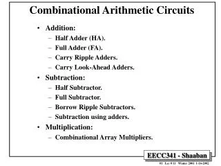
Binary Adders • Half Adder(HA): A circuit that will add two bits and produce a sum and carry result. • Full Adder(FA): A circuit that will add a carry bit from another HA or FA and two operand bits to produce a sum and carry result.
Basic HA Addition • Binary Two Bit Addition Rules 0 + 0 = 00 0 + 1 = 01 1 + 1 = 10 Figure 6.1 Half Adder
HA Circuit • Basic Equations S = A xor B, C = A and B where S = Sum and C = Carry. • Truth Table for HA Block Figure 6.2 A B C S 0 0 0 0 0 1 0 1 1 0 0 1 1 1 1 0
Full Adder Basics • Adds a CIN input to the HA block. • Equations are modified as follows. • C = ((A xor B) and CIN) or (A and B). • S = A xor B xor CIN. • A FA can be made from two HA blocks and an OR Gate.
FA Circuit • Two HA Full Adder Circuit. Figure 6.6
Parallel Adders • N-Bit Multiple Adder (FA Stages) A1 A S A2 A S AN A 0 CI CO CI CO CI B1 B B2 B BN B S1 S2 SN
Ripple Carry I • In the N-Bit Parallel Adder (FA Stages) the Carryout is generated by the last stage (FAN). • This is called a Ripple Carry Adder because the final carryout (Last Stage) is based on a ripple through each stage by CIN at the LSB Stage. Figure 6.11
Ripple Carry II • Each Stage will have a propagation delay on the CIN to COUT of one AND Gate and one OR Gate. • A 4 Bit Ripple Carry Adder will then have a propagation delay on the final COUT of 4 X 2 = 8 Gates. • A 32 Bit adder such as in a MPU in a PC could have a delay of 64 Gates.
Look Ahead Carry I • Fast Carry or Look Ahead Carry: A combinational network that generates the final COUT directly from the operand bits (A1 to AN, B1 to BN). It is independent of the operations of each FA Stage( as the ripple carry is).
Look Ahead Carry II • Fast Carry has a small propagation delay compared to the ripple carry. • The fast carry delay is 3 Gates for a 4-Bit Adder compared to 8 for the Ripple Carry. • Cn = AnBn + Cn-1(An + Bn)
4-bit Fast Carry Circuit Fig. 6.12
Subtractor (2s Complement) I • The concept of Subtraction using 2s Complement addition allows a Parallel FA to be used. • This could be used in a MPU ALU (Arithmetic Logic Unit) for Subtraction. • The subtract operation involves adding the inverse of the subtrahend to the minuend and the add a 1.
2s Complement Subtractor Fig. 6.14 Ex) 0101-0011 2’s comp. Of 0011 0011 1100(1’s) +1 1101 0101(+5) + 1101(-3) 1 0010(+2) discard carry
Subtractor (2s Complement) II • Difference = A - B = A + !B + 1. • This operation can be done in a parallel N-Bit FA by Inverting (B1 to BN) and connecting CIN at the LSB Stage to +5V. • The circuit can be modified to allow either the ADD or SUBTRACT Operation to be performed. Figure 6.16
2s Complement Adder/Subtractor Fig. 6.15
Structured VHDL Design I • Hierarchy: A group of design entities associated in a series of levels (the hierarchy) in which complete designs form portions or subsections of the upper design. • Component: A complete VHDL Design Entity that can be used as part of a higher level file in a hierarchical design.
Structured VHDL Design II • Port: An Input or Output of a VHDL design entity or component. • Component Declaration Statement: A statement that defines the I/O Port Names of a component in a VHDL Design Entity. • Component Instantiation Statement: A statement that maps port names of a VHDL component to the port names, internal signals, or variables of a higher-level VHDL design entity. • The following slide will illustrate a Full Adder VHDL Design using a Single FA Component.
Full Adder VHDL • Basic Full Adder (1 Bit Add plus carry) ENTITY full_add IS PORT( a, b, c_in : IN BIT; c_out, sum : OUT BIT); END full_add; ARCHITECTURE adder OF full_add IS BEGIN C_OUT <= ((a XOR b) AND C_IN) OR (a AND b); SUM <= (a XOR b) XOR c_in; END adder;