Download
1 / 9
130 likes | 573 Views
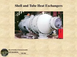
DESIGN OF SHELL AND TUBE HEAT EXCHANGER. BY-RAHUL OMAR 0616651020 B.TECH.F(CH). Heat Exchanger Includes. Shell Tubes Working fluids. Heat Exchanger Shell. More expensive to manufacture than tubes Material. Heat Exchanger Tubes. Number of tubes Tube wall thickness

E N D
DESIGN OF SHELL AND TUBE HEAT EXCHANGER BY-RAHUL OMAR 0616651020 B.TECH.F(CH)
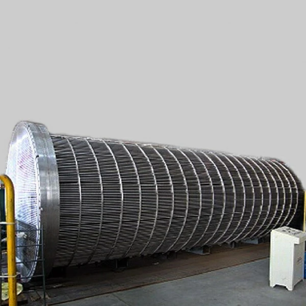
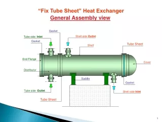
Heat Exchanger Includes • Shell • Tubes • Working fluids
Heat Exchanger Shell • More expensive to manufacture than tubes • Material
Heat Exchanger Tubes • Number of tubes • Tube wall thickness • Tube outside diameter • Tube length • Tube passes • Tube material • Tube layout • Tube pitch
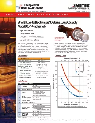
Heat Exchanger Tubes • Number of tubes • Depends on flow rate & available pressure drop • Too many/few tubes • Tube wall thickness • All tubes have standards • Tube outside diameter • Small diameter means larger pressuredrop
Tube length • Typical lengths – 8, 12, 15, 20 ft. • Tube passes • Number of times fluid moves from one • side of HE to other • The more passes the greater the velocity
Tube material • Meeting requirements • Cost • Thermal properties • Tube layout • Square • Tube pitch
Heat Exchangers Fluids • Viscous fluids belong on shell side because usually improves heat transfer rate • Fouling and erosion exist; higher velocity of fluid reduces build-up
Problem Statement 4500kg/hr of ammonia vapour at 6.7 bar pressure is to be cooled from 1200C to 400C, using cooling water.The maximum supply temp. of cooling water available is 300C &the outlet temp. is to be restricted to 400C.The pressure drop over the exchanger must not exceed 0.5 bar for the ammonia stream & 1.5 bar for the cooling water.