Steps Toward a Prototype Atomic Clock
430 likes | 453 Views
Steps Toward a Prototype Atomic Clock. Nathan Belcher Senior Research Midterm Talk 12.13.07. Acknowledgements. Prof. Irina Novikova Prof. Eugeniy Mikhailov Chris Carlin. Outline. Overall goal of project Background Hardware DAVLL Data and results Future work. Overall Goal of Project.

Steps Toward a Prototype Atomic Clock
E N D
Presentation Transcript
Steps Toward a Prototype Atomic Clock Nathan Belcher Senior Research Midterm Talk 12.13.07
Acknowledgements • Prof. Irina Novikova • Prof. Eugeniy Mikhailov • Chris Carlin
Outline • Overall goal of project • Background • Hardware • DAVLL • Data and results • Future work
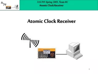
Overall Goal of Project • To create a prototype atomic clock • Need: • Laser • Transition • Laser Frequency Locking System • Counter
Overall Goal of Project continued • Have: • Vertical-cavity surface-emitting laser (VCSEL) • Transition in rubidium-87 --> 5S_1/2 to 5P_1/2 (794.7 nm) • Dichroic atomic vapor laser locking (DAVLL) • Counter
Outline • Overall goal of project • Background • Hardware • DAVLL • Data and results • Future work
Background • Atomic transition in rubidium-87 • 5S_1/2 to 5P_1/2
Background continued • Use electromagnetically induced transparency to measure transmitted light • The closer to hyperfine splitting resonance, the more transmission • Counter locked to maximum transmission which corresponds to clock frequency
Background continued • Lambda system requires two fields at different frequencies • Problem: inherent in lasers are small random shifts in frequency around a set frequency (“jumps”) • Bigger problem: if two lasers are physically separate, the “jumps” are random
Background continued • Solution: use phase modulation to create two fields out of one physical laser • Why? Both fields “jump” with each other so relative frequency can be set by external generator • Creates carrier with sideband comb
Background continued • Three phase modulation formulas
Background continued • Carrier to sideband spacing determined by input frequency
Outline • Overall goal of project • Background • Hardware • DAVLL • Data and results • Future work
Hardware • VCSEL
Hardware continued • Temperature stability
Hardware continued • VCSEL constant current source
Hardware continued • Measuring setups • Phase modulation measurement
Hardware continued • Fabry-Perot cavity • Second mirror moved by piezoelectric • Piezoelectric controlled by voltage source, with low frequency modulation
Hardware continued • Another measuring setup • Finding rubidium resonances • Vapor cell can be either isotropically pure Rb-87 or natural abundance Rb-85 and -87
Hardware continued • Modulators • Commercial digital synthesizer (Agilent E8275D) • Up to 14 dBm of power at very precise frequencies • Stellex Mini-YIG crystal oscillator • Current controlled tunable crystal with frequencies ranging from 5.95 GHz to 7.15 GHz at 15 dBm
Hardware continued • Inside of Stellex oscillator
Hardware continued • Stellex oscillator calibration measurements
Hardware continued • Solenoid and shields • External non-homogeneous fields that interact with vapor cell, shifting state frequencies • Need to control field vapor cell feels, so surround cell with solenoid to produce constant homogeneous magnetic field and shields to limit outside magnetic fields
Outline • Overall goal of project • Background • Hardware • DAVLL • Data and results • Future work
DAVLL • Allows locking of frequency of VCSEL to specific rubidium resonance frequency
DAVLL continued • Optical hardware
DAVLL continued • Absorption and differential spectra
DAVLL continued • Electronics are used to amplify the raw signal from the optics and adjust the current to the laser accordingly • Example: if laser’s frequency is higher than zero point on raw signal, electronics will supply less current so frequency decreases
DAVLL continued • Flow chart of electronics
DAVLL continued • There have been issues with the raw signal • Raw signal offset with respect to zero point • This offset causes tension between raw signal and feedback to laser • Makes us question whether laser locked on resonance or if signals not representative of locking
DAVLL continued • Auxiliary input useful to find correct range laser needs to be in for resonances • Some work done to make voltage scales of function generator and raw signal approximately equivalent • This will allow us to compare Aux and Raw Signals to make sure locked on resonance
Outline • Overall goal of project • Background • Hardware • DAVLL • Data and results • Future work
Data and Results • VCSEL Modulation • Used Agilent E8275D and Stellex oscillator • With Agilent, saw 1-to-1 sideband-to-carrier ratio at 14 dBm at 6.834 GHz • With Stellex, saw sidebands greater than carrier at 15 dBm at 6.834 GHz
Data and Results continued • Agilent modulation
Data and Results continued • Stellex modulation
Data and Results continued • Rubidium resonances • Two vapor cells: isotropically pure Rb-87 and natural abundance Rb-85 and -87 • Pure Rb-87 cell inside shields, used to achieve EIT • Mixed Rb-85 and -87 cell used in DAVLL as reference cell
Data and Results continued • Isotropically pure Rb-87 cell
Data and Results continued • Natural abundance Rb-85 and -87 cell
Data and Results continued • Electromagnetically induced transparency (EIT) • Occurs when all electrons are driven to ‘dark’ state that does not interact with either electromagnetic field • Laser has 100% transmission
Data and Results continued • EIT in Irina’s pure vapor cell
Data and Results continued • EIT in my pure vapor cell
Future Work • True DAVLL locking • Understand offset issues and work through them • Add counter to system • Test clock against frequency from Agilent