Download
1 / 58
580 likes | 729 Views
Optics Basics. A Physics MOSAIC MIT Haystack Observatory RET 2010. Background image from NASA. Representing Light.

E N D
Optics Basics A Physics MOSAIC MIT Haystack Observatory RET 2010 Background image from NASA
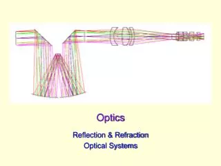
Representing Light As we have already seen, light (and all electromagnetic waves) consists of electric and magnetic fields oscillating perpendicular to each other and to the direction of wave propagation. While a source of electromagnetic radiation will (generally) send waves out in all directions from the source, it is often convenient to represent these waves as rays, traveling in straight lines and represented by arrows. Some sources, like light bulbs and stars, send light rays out in all directions. Image by SKMay Other sources, like lasers, send out light rays in (primarily) one direction. Thomasbrightbill, from flickr, Creative Commons
Inverse Square Law • Like sound, the gravitational force, and the electrostatic force, light (and other electromagnetic waves) follow an inverse square law for intensity. • As the distance from a source of light increases, the intensity detected decreases with the square of the distance. • This should make some sense, since the light from the source is being spread over larger areas (proportional to distance2) as the distance increases. Image from NASA
Which Object is Brightest? Image found at Nasa.gov, photo credit: Dave Jurasevich, Mt. Wilson Observatory
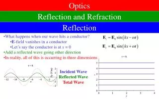
What does it mean to be reflective? As with other types of waves, light reflects off boundaries it encounters at changes in media. Materials absorb some of the light that encounters their surface, transmit some of the light, and reflect some of the light. If most of the light is reflected rather than absorbed, we think of it as a reflective surface. This depends on the chemical properties of the material. Glass transmits most of the light through the medium, but some is reflected. Why can you see yourself in your windows at night but see outside during the day? Reflection for Light
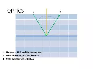
Fermat’s Principle of Least Time states that of all the possible paths for light to take between two points, it will take the one that requires the least amount of time. For single medium situations, this corresponds to straight paths. The path of least time for a ray to reflect off a mirror results in equal angles of incidence and reflection. This is called the Law of Reflection. Fermat’s Principle of Least Time
Law of Reflection: The angle of incidence of a ray equals the angle of reflection. Both angles should be measured from the normal, or line perpendicular to the surface. The law of reflection applies to all reflection, regardless of the surface or the type of wave being reflected. Law of Reflection Image from Wikipedia, Drawn by Johan Arvelius 2005-09-26, Creative Commons
If the surface is smooth, the reflection is specular. That is, the light rays all reflect in the same direction. If the surface is not smooth, the reflection is diffuse. That is, the light rays reflect in different directions Diffuse and Specular Reflection Images from http://twistedphysics.typepad.com/cocktail_party_physics/optics/
The “smooth”-ness of a surface depends on the size of the irregularities on the surface compared to the wavelength of the wave being reflected. This means that what constitutes smooth for radio waves is different than for visible light or x-rays. (Remember the EM Spectrum) In order to be considered smooth, any bumps on the surface must be smaller than the size of the wavelength being reflected. For telescopes, microscopes, and other high precision devices, even smaller irregularities are tolerable. Typically, astronomers seek 1/20l smoothness for their instruments. Smooth?
Smooth to What? James Clerk Maxwell Telescope Water on Calm Day Satellite TV Dish Image from National Research Council of Canada
In conclusion, in order to be “shiny” for a particular electromagnetic wave, a surface must be both Reflective: it must neither absorb nor transmit the majority of the light incident upon it. Smooth: with bumps and irregularities on the same size scale of the wavelength of the radiation being reflected Two Properties of Being Shiny
The MOSAIC system reflects radio waves at a frequency of 11.072 GHz that come from ozone in Earth’s mesosphere onto a feed at the focal point of the dish. Because it reflects radio waves, it does not look shiny in visible light, but does look shiny to the 11.072 GHz radiation we are interested in. MOSAIC and reflection
By making a shiny surface in an appropriate curved shape, you can create a mirror where parallel rays approaching the mirror reflect to a single point (the focal point). This is still an example of specular reflection, and each individual ray reflects according to the law of reflection. Basics of Concave Mirrors qi qr qi qr qi qr From Wikipedia, Image by AndrewBuck, Creative Commons
Focal Length (f) Distance between the mirror and the focal point (F). Depends on radius curvature of mirror (r): for spherical mirrors, f = r/2 Light Gathering Power Ability of the mirror to gather light. Especially important for telescopes. Depends on area of telescope. Proportional to (diameter)2 Resolution Ability of the mirror to differentiate small features. Depends on wavelength being observed and diameter of telescope. Improves proportional to diameter of telescope. Improves indirectly with wavelength. Properties of Concave Mirrors Image from Telescopes from the Ground Up, Amazing Space, http://amazing-space.stsci.edu/resources/explorations/groundup/, Image in public domain
Arecibo Radio Telescope The 300 m telescope at Arecibo, Puerto Rico is designed to observe and transmit radio waves to and from space. As we have seen, radio waves have a much longer wavelength than the visible spectrum. How is that reflected in the size of this telescope? Its smoothness? Photo by SKMay
Two Types of Curved Mirrors • Curved mirrors are either concave or convex in shape. • As we have seen, concave mirrors tend to converge light rays (and thus are used in telescopes). • Convex mirrors tend to diverge light rays. • Both types of curved mirrors can produce images, and both have practical applications. Images from Telescopes from the Ground Up, Amazing Space, http://amazing-space.stsci.edu/resources/explorations/groundup/. Image in public domain
Special Rays for Concave Mirrors • Using what we know about the properties of concave mirrors, we can develop some shortcuts for tracing rays that encounter the surface. • Special Rays for Concave Mirrors • A ray approaching the mirror parallel to the principal axis will reflect through the focal point. • A ray approaching the mirror along a path through the focal point will reflect parallel to the principal axis. • A ray approaching the mirror along a path through the center of curvature (for a spherical mirror) will reflect back along its incoming path. (The angle of incidence is zero.) • A ray encountering the mirror at the center will reflect with an angle of reflection equal to the angle of incidence. (The normal is the principal axis.) 4 1 3 • C • F principal axis 2
Special Rays for Convex Mirrors • Instead of focusing parallel rays to a single focal point, a convex mirror disperses incoming parallel rays, as if they are coming from a single focal point, located behind the mirror. • Using this, we can develop the same sort of shortcuts for rays that we did with concave mirrors. • Special Rays for Convex Mirrors • A ray approaching the mirror parallel to the principal axis will reflect as if it coming from the focal point. • A ray approaching the mirror along a path directed towards the focal point will reflect parallel to the principal axis. • A ray approaching the mirror along a path directed towards the center of curvature (for a spherical mirror) will reflect back along its incoming path. (The angle of incidence is zero.) • A ray encountering the mirror at the center will reflect with an angle of reflection equal to the angle of incidence. (The normal is the principal axis.) 4 1 • F • C principal axis 3 2
Helpful facts about image formation Images that form from the actual convergence of light rays are called real images. These are formed in front of mirrors. Images that form from the apparent convergence of light rays are called virtual images. These are formed behind mirrors, as in the flat mirror you may have in your bedroom or bathroom. Your brain always interprets a light ray coming into your optical system as having traveled in a straight path. Image Formation from Curved Mirrors
When the object is located closer to the mirror than the focal point, a virtual, upright, larger image is produced. The image is located behind the mirror. Ray Diagram: Concave Mirrors do < f The image is located using two special rays. Light leaves the object in all directions, but if we choose to sketch the path of rays following our special ray paths, we can easily find the point of convergence, which, in this case, is behind the mirror. Images from Wikipedia, user Cronholm144, Creative Commons
Ray Diagrams: Concave Mirrors do = f No image is formed when the object is placed at the focal point. All light rays reflect off the mirror parallel to each other, so there is no convergence. f < do < 2f A real, inverted, larger image is formed when the object is placed between the focal point (F) and the center of curvature (C or 2F). The image is beyond 2F (or C). Images from Wikipedia, user Cronholm144, Creative Commons
Ray Diagrams: Concave Mirrors do= 2f A real, inverted, same-size image is formed when the object is placed at the center of curvature (C or 2F). The image is also located at 2F (or C). do> 2f A real, inverted, smaller image is formed when the object is placed beyond the center of curvature (C or 2F). The image is located between the F and 2F (or C). Images from Wikipedia, user Cronholm144, Creative Commons
No matter there the object is placed near a flat mirror, a virtual, upright, and same-size object will be produced. The image is located behind the mirror at the same distance as the object. Ray Diagrams: Flat Mirrors From Wikipedia, user Fffred, Public Domain
No matter where the object is located relative to the surface of the convex mirror, a virtual, upright, smaller image is produced. The image is located behind the mirror. Ray Diagrams: Convex Mirrors Images from Wikipedia, user Cronholm144, Creative Commons
Applications of Mirrors James Webb Space Telescope Image from NASA The Bean, Chicago Image by SKMay Side View Mirror Image by SKMay Magnifying Mirror Image by steveloya, Flickr, Creative Commons Rearview Mirror Image by SKMay Security Mirror Image by Leo Reynolds, Flickr, Creative Commons
Depending on the location of the object relative to the focal point, concave mirrors can produce real images that are larger, the same size, or smaller than the object or virtual images that are larger than the object. Convex mirrors always produce virtual images that are smaller than the object. Flat mirrors always produce virtual images that are the same size as the object. Summary: Types of Images and Sizes
The relationship between the position of an object, image, and focal length of the mirror is given by the mirror equation: This equation is completely consistent with the images produced using ray diagrams on the earlier slides. In order to take advantage of the equation, we must be very careful with signs. Focal length (f): positive for converging mirrors (concave), negative for diverging mirrors (convex) Object distance (do): positive for real objects Image distance (di): positive for real images (in front of mirror), negative for virtual images (behind mirror) Mirror Equation
The amount that an image is enlarged or reduced as compared to the object is expressed in its magnification (m). Magnification is defined as the ratio of the height of the image (hi) to the height of the object (ho). It is also equivalent to the opposite of the ratio of the image distance to the object distance. The height of the image (hi) will be positive when the image is upright (and therefore virtual) and negative when the image is inverted (and therefore real). Magnification
Spherical reflectors introduce an aberration (error) in focal point. This is called spherical aberration, and consists of the light rays not coming to a perfect focus at a single point. This aberration does not exist when a parabola is used. Because of the properties of a parabola, light rays that come into the mirror parallel to the center line reflect exactly to a single focal point. Spherical Aberration and Parabolas Image from Telescopes from the Ground Up, Amazing Space, http://amazing-space.stsci.edu/resources/explorations/groundup/. Image in public domain
Applications of Parabolic Optics From Wikipedia, Creative Commons, User MatějBaťha The world's larges solar energy dish at the Ben-Gurion National Solar Energy Center in SdeBoker, Israel. From Wikipedia, Creative Commons, user David Shankbone. Parabolic Hot Dog Cooker, from nycg46, found on Flickr From Wikipedia, Creative Commons, User Duk
Design: Uses only part of a parabola, allowing the focal point to be below the dish doing the receiving. Advantages The receiver (located at the focal point) does not need to block any of the signal Note that the dish appears to be pointing in a different direction than it actually is. Offset Parabola Image of Green Bank Radio Telescope (Green Bank, WV) from NRAO / AUI / NSF, from RET 2009
MOSAIC’s Offset Parabola Like the Green Bank Radio Telescope, MOSAIC (and all small television satellite dishes) are offset parabolas. While this dish appears to be pointed towards the ground, it is actually pointing 8˚ above the horizon. Images by SKMay
Refraction Basics Recall that the speed of a wave depends on the properties of the medium it is traveling through. For light, the speed of the wave depends on the optical density of the medium. Light only travels at c (3.0 x 10⁸ m/s), the speed of light in a vacuum, when it is in a vacuum. (Go figure!) Index of Refraction We can quantify the effect of different media on the speed of light with the index of refraction (n). Greater n, slower speeds. Refraction
Some Indices of Refraction What is the speed of light in water? Still pretty fast!
Refraction is the bending of a wave due to a change in the speed of the wave in different media. This can be thought of a consequence of Fermat’s Principle. Light travels more slowly in optically dense media, so it spends less time in them. Light travels more quickly in media that are less optically dense, thus spending more time. Refraction and Fermat’s Principle of Least Time
Example: Fermat’s Principle for Lifeguards The lifeguard will spend more time running along the beach to get to the flailing swimmer than in the water, because he is a faster runner than he is a swimmer. How would this ideal path change if the lifeguard were a seal? sand Lifeguard water flailing swimmer I’m a much better swimmer than runner! Image by SKMay
Example: Fermat’s Principle for Light The light from the laser will take a path that spends more time in air than water, since it travels faster in air than it does in water. Note that this results in a smaller angle of refraction than the angle of incidence, since both are measured from the normal. air laser pointer qi water qr target
Note that Light bends towards the normal when entering a slower medium (higher n) qi > qrwhen ni < nr Light bends away from the normal when entering a faster medium (lower n) qi< qr when ni> nr The amount of bending will depend on how much slower or faster the new medium is. Note also The light is partially reflected (following the law of reflection) at each boundary. Light Rays in Media air glass qi qr qi
WillebrordSnellius (the disputed funniest name in all of physics) recorded the quantitative law governing refraction of light in 1621. The law was previously discovered in 984 by IbnSahl. Ptolemy also collected the data in table form, but didn’t know about trigonometry. Still, there’s a nice song about Snell and his (dubious) accomplishment. Snell’s Law states As was true for the Law of Reflection, all angles must be measured from the normal. Snell’s Law Image from Wikipedia, user Oleg Alexandrov, Public Domain
When a ray of light encounters a medium with a lower optical density than the one it is currently in (lower n, higher speed), there are three possibilities for its behavior. For low angles of incidence, the ray will refract, bending away from the normal. At some critical angle, the angle of refraction will be 90˚. For angles of incidence greater than the critical angle, the ray will reflect perfectly, staying within the incident material. This is called total internal reflection. When a ray of light encounters a medium with higher optical density, there will always be refraction. There is no critical angle in this case. Snell’s Law and Total Internal Reflection
Critical Angles and TIR angle of incidence less than critical angle qi < qc angle of incidence equal to critical angle qi = qc angle of incidence greater than critical angle qi > qc qr Air n = 1.00 Air n = 1.00 qr Air n = 1.00 qi qrl qi qrl qi qrl Water n = 1.33 Water n = 1.33 Water n = 1.33 For the partially reflected ray: qi = qrl. For the refracted ray: ni sin qi = nr sin qr For the totally reflected ray: qi = qrl. There is no refracted ray! For the partially reflected ray: qi = qrl. For the refracted ray: ni sin qc= nr sin 90˚ sin qc = nr/ni
Total Internal Reflection Wikipedia, user Hustvedt, Creative Commons Wikipedia, user Mina Zinkova, Creative Commons Wikipedia, Public Domain
By cleverly changing the shape of a refractive medium, you can produce a lens. Parallel rays approaching the lens converge to a single point. Each individual light ray bends according to Snell’s Law. Convex Lens Basics Images from Telescopes from the Ground Up, Amazing Space, http://amazing-space.stsci.edu/resources/explorations/groundup/. Image in public domain
Focal Length Depends on n The greater the change in the speed of light, the greater the bending, and therefore, the smaller the focal length. Depends on curvature The smaller the radius, the greater the bending, and therefore, the smaller the focal length. Light Gathering Power: as with concavemirrors, proportional to area. Resolution: as with concave mirrors, improves with diameter and gets worse as the wavelength of the observed radiation increases. Properties of a Convex Lens Image by SKMay
By cleverly changing the shape of the medium, you can produce a lens. Just as with mirrors, lenses can be either concave or convex in shape. While Snell’s Law governs the interaction of each light ray with the lens, we can develop some shortcuts by considering special rays, as we did with mirrors. Two Types of Lenses Images from Telescopes from the Ground Up, Amazing Space, http://amazing-space.stsci.edu/resources/explorations/groundup/. Image in public domain
Special Rays for Convex Lenses • Using what we know about the properties of convex lenses, we can develop some shortcuts for tracing rays that encounter the surface. • Special Rays for Convex Lenses • A ray approaching the lens parallel to the principal axis will refract through the focal point on the opposite of the lens. • A ray approaching the lens along a path through the focal point will refract parallel to the principal axis on the opposite side of the lens. • A ray passing through the optical center of the lens will be undeflected. 2 3 1 • F • F • 2F • 2F principal axis
Special Rays for Concave Lenses • Using what we know about the properties of concave lenses, we can develop some shortcuts for tracing rays that encounter the surface. • Special Rays for Convex Lenses • A ray approaching the lens parallel to the principal axis will refract as if it is coming from the focal point on the side of the lens it comes from. • A ray approaching the lens along a path toward the focal point on the opposite site of the lens will refract parallel to the principal axis. • A ray passing through the optical center of the lens will be undeflected. 3 1 • F • 2F • F • 2F principal axis 2
Just as we saw with image formation from mirrors, we can note the following helpful facts: Images that form from the actual convergence of light rays are called real images. These are formed on the opposite side of a lens as the object. Images that form from the apparent convergence of light rays are called virtual images. These are formed on the same side of the lens as the object. Your brain always interprets a light ray coming into your optical system as having traveled in a straight path. Image Formation from Lenses
Just as with mirrors, we can identify the nature and location of an image formed by a lens by tracing a few special rays leaving the object as they refract through the lens and ultimately converge. Ray Diagrams: Convex Lens A A do > 2f The image produced is real, inverted, and smaller than the object. The image is located between F and 2F. A A do = 2f The image produced is real, inverted, and the same size as the object. The image is located at 2F.
Ray Diagrams: Convex Lens A A 2f > do> f The image produced is real, inverted, and larger than the object. The image is located beyond 2f. A do = f There is no image produced. All refracted rays emerge from the lens parallel to each other.