Download
1 / 51
510 likes | 681 Views
TECI 185 Routing Protocols and Concepts Jack Yon Western Colorado Community College jyon@mesastate.edu Last Updated: 4/14/2009. Chapter 10 Link State Routing Protocols. Topics. Step 5: Constructing a Link-State Database Shortest-Path First (SPF) Tree

E N D
TECI 185 Routing Protocols and Concepts Jack Yon Western Colorado Community College jyon@mesastate.edu Last Updated: 4/14/2009 Chapter 10Link State Routing Protocols
Topics • Step 5: Constructing a Link-State Database • Shortest-Path First (SPF) Tree • Implementing Link-State Routing Protocols • Advantages of a Link-State Routing Protocol • Requirements of a Link-State Routing Protocol • Comparison of Link-State Routing Protocol • Link-State Routing • Link-State Routing Protocols • Introduction to the SPF Algorithm • Link-State Routing Process • Step 1: Learning About Directly Connected Networks • Step 2: Sending Hello Packets to Neighbors • Step 3: Building the Link-State Packet • Step 4: Flooding Link-State Packets to Neighbors
Link-State Routing Protocols Introduction to the SPF Algorithm Link-State Routing Process Step 1: Learning About Directly Connected Networks Step 2: Sending Hello Packets to Neighbors Step 3: Building the Link-State Packet Step 4: Flooding Link-State Packets to Neighbors Step 5: Constructing a Link-State Database Shortest-Path First (SPF) Tree Link-State Routing
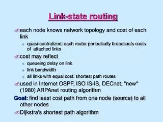
Introduction Link-State Routing Protocols • Link-state routing protocols • AKA shortest path first protocols • Uses Edsger Dijkstra’s shortest path first (SPF) algorithm. (later) • Reputation of being much more complex than their distance vector counterparts. • Functionality and configurationnot complex • Algorithm is easy to understand
Introduction Link-State Routing Protocols • Distance vector routing protocols - road signs • Distance and vector • Link-state routing protocols - road map • Topological map used by each router • Each router determines the shortest path to each network Link-State Distance Vector
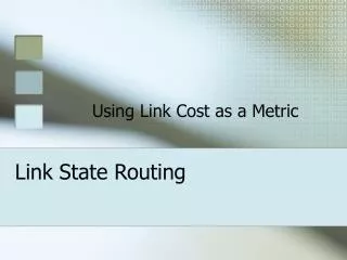
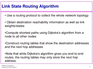
Introduction to the SPF Algorithm • Dijkstra’s algorithm is commonly referred to as the shortest path first (SPF) algorithm. • Shortest path first is really the objective of every routing algorithm.
27 to R3 LAN Introduction to the SPF Algorithm 20 The cost of the shortest path for R2 to R3 LAN = 27 (20 + 5 + 2 = 27). 5 2 • Each router calculates the SPF algorithm and determines the cost from its own perspective. (more later)
Introduction to the SPF Algorithm SPF for R1 • The shortest path is not necessarily the path with the least number of hops.
Shortest Paths for each Router SPF for R1 SPF for R2 SPF for R4 SPF for R3 SPF for R5
Link-State Routing Process 1. Each router learns about its own links, its own directly connected networks. (Interface is “up”) 2. Each router is responsible for meeting its neighbors on directly connected networks. (OSPF Hello packets) 3. Each router builds a link-state packet (LSP) containing the state of each directly connected link. (neighbor ID, link type, and bandwidth) 4. Each router floods the LSP to all neighbors, who then store all LSPs received in a database. • Neighbors then flood the LSPs to their neighbors until all routers in the area have received the LSPs. 5. Each router uses the database to construct a complete map of the topology and computes the best path to each destination network. • The SPF algorithm is used to construct the map of the topology and to determine the best path to each network. (Road map) • All routers will have a common map or tree of the topology, but each router will independently determine the best path to each network within that topology. • Detail and explanations are coming next!
Step 1: Learning About Directly Connected Networks • Step 1: Each router learns about its own links, its own directly connected networks. • Interface configured with an IP address/subnet mask. • Directly connected networks are now part of the routing table • Regardless of the routing protocols used.
Step 1 • A link is an interface on a router. • For the link participate in the link-state routing process, it must be: • In the up state. • Included in one of the network statements.
Step 1 • Link states - Information about the state of a router’s links • This information includes interface’s: • IP address/mask • Type of network • Ethernet (broadcast) or serial point-to-point link • Cost of that link • Any neighbor routers on that link
Step 1 Initially: • Router unaware of any neighbor routers on the link. • Learns of neighbor when receives a Hello packet from the adjacent neighbor.
Step 2: Sending Hello Packets to Neighbors • Step 2: Each router is responsible for meeting its neighbors on directly connected networks. • Use a Hello protocol to discover any neighbors on their links. • A neighbor is any other router that is enabled with the same link-state routing protocol.
Step 2: Sending Hello Packets to Neighbors Hello packets • “Keepalive” function • Stops receiving Hello packets from a neighbor, that neighbor is considered unreachable and the adjacency is broken.
Step 3: Building the Link-State Packet • Step 3: Each router builds a link-state packet (LSP) containing the state of each directly connected link.
Step 3: Building the Link-State Packet A simplified version of the LSPs from R1 • After established its adjacencies • Builds its LSPs • Link-state information about its links. • Sends LSPs out interfaces where it has established adjacencies with other routers. • R1 not sent LSPs out its Ethernet interface.
Step 4: Flooding Link-State Packets to Neighbors • Step 4: Each router floods the LSP to all neighbors, who then store all LSPs received in a database. • Each router floods its link-state information to all other link-state routers. • When a router receives an LSP from a neighboring router, sends that LSP out all other interfaces, except the interface that received the LSP. • Flooding effect of LSPs throughout the routing area.
Step 4: Flooding Link-State Packets to Neighbors • Link-state routing protocols calculate the SPF algorithm after the flooding is complete.
Step 4: Flooding Link-State Packets to Neighbors • An LSP needs to be sent only: • During initial startup of the router or of the routing protocol process on that router • Whenever there is a change in the topology, • link going down • link coming up • neighbor adjacency being established • neighbor adjacency being broken
Link State Database for R1 Step 5: Constructing a Link-State Database • Step 5 (Final Step): Each router uses the database to construct a complete map of the topology and computes the best path to each destination network. • After propagation of LSPs • Each router will then have an LSP from every link-state router. • LSPs stored in the link-state database.
Running SPF Algorithm • Each router in the routing area can now use the SPF algorithm to construct the SPF trees that you saw earlier.
Step 5: Constructing a Link-State Database SPF Tree for R1 • With a complete link-state database, R1 can use shortest path first (SPF) algorithm to calculate shortest path to each network. • SPF algorithm results in an SPF tree.
Building the Shortest Path First (SPF) Tree Link State Database for R1 • At first, the tree (topology) only includes its directly connected neighbors. • Using the link-state information from all other routers, R1 can now begin to construct an SPF tree of the network with itself at the root of the tree.
R1 Processes the LSPs from R2 Red: New information for tree. • The SPF algorithm begins by processing the following LSP information from R2: • Connected to neighbor R1 on network 10.2.0.0/16, cost of 20 • Connected to neighbor R5 on network 10.9.0.0/16, cost of 10 • Has a network 10.5.0.0/16, cost of 2
R1 Processes the LSPs from R3 Red: New information for tree. • The SPF algorithm begins by processing the following LSP information from R3: • Connected to neighbor R1 on network 10.3.0.0/16, cost of 5 • Connected to neighbor R4 on network 10.7.0.0/16, cost of 10 • Has a network 10.6.0.0/16, cost of 2
R1 Processes the LSPs from R4 Red: New information for tree. • The SPF algorithm begins by processing the following LSP information from R4: • Connected to neighbor R1 on network 10.4.0.0/16, cost of 20 • Connected to neighbor R3 on network 10.7.0.0/16, cost of 10 • Connected to neighbor R5 on network 10.10.0.0/16, cost of 10 • Has a network 10.8.0.0/16, cost of 2
R1 Processes the LSPs from R5 Red: New information for tree. • The SPF algorithm begins by processing the following LSP information from R5: • Connected to neighbor R2 on network 10.9.0.0/16, cost of 10 • Connected to neighbor R4 on network 10.10.0.0/16, cost of 10 • Has a network 10.11.0.0/16, cost of 2
SPF Tree • R1 has now constructed the complete SPF tree.
Determining the Shortest Path • Using the SPF tree, SPF algorithm results in the shortest path to each network. • Note: Only the LANs are shown in the table, but SPF can also be used to determine the shortest path to each WAN link network.
2 Determining the Shortest Path 20 Network 10.5.0.0/16 via R2 Serial 0/0/0 at a cost of 22
Determining the Shortest Path 2 5 Network 10.6.0.0/16 via R3 Serial 0/0/1 at a cost of 7
Determining the Shortest Path 5 10 Network 10.7.0.0/16 via R3 Serial 0/0/1 at a cost of 15
Determining the Shortest Path 5 10 Network 10.8.0.0/16 via R3 Serial 0/0/1 at a cost of 17 2
Determining the Shortest Path 10 20 Network 10.9.0.0/16 via R2 Serial 0/0/0 at a cost of 30
Determining the Shortest Path 5 10 Network 10.10.0.0/16 via R3 Serial 0/0/1 at a cost of 25 10
Determining the Shortest Path 5 2 10 Network 10.11.0.0/16 via R3 Serial 0/0/1 at a cost of 27 10
Determining the Shortest Path • Each routerconstructs its own SPF tree independently from all other routers. • Link-state databases must be identical on all routers.
Generating a Routing Table from the SPF Tree SPF Tree for R1 R1 Routing Table NetworkCostExit-InterfaceNext-hop • These paths listed previously can now be added to the routing table. • The routing table will also include • Directly connected networks • Routes from any other sources, such as static routes. • Packets will now be forwarded according to these entries in the routing table.
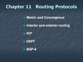
Advantages of a Link-State Routing Protocol Requirements of a Link-State Routing Protocol Comparison of Link-State Routing Protocol Implementing Link-State Routing Note: Chapter 11 discusses the implementation and configuration of a link-state routing protocol, OSPF.
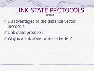
Advantages of a Link-State Routing Protocol • Builds a Topological Map • Distance vector routing protocols do not have a topological map of the network. • Using the SPF tree, each router can independently determine the shortest path to every network.
Advantages of a Link-State Routing Protocol • Fast Convergence • Immediately flood the LSP out all interfaces except for the interface from which the LSP was received. • The lack of a hold-down timer, which is a distance vector routing protocol feature designed to give the network time to converge. • Changes in the topology are flooded immediately using LSPs.
Event-Driven Updates • Only send out an LSP when there is a change in the topology. • Only the information regarding the affected link. • Unlike some distance vector routing protocols (RIP), link-state routing protocols do not send periodic updates. • OSPF routers do flood their own link states every 30 minutes. • This is known as a paranoid update and is discussed in the following chapter.
Hierarchical Design • Link-state routing protocols such as OSPF and IS-IS use the concept of areas. • Better route aggregation (summarization) • Isolation of routing issues within an area. • Multi-area OSPF and IS-IS are discussed further in CCNP.
Link State Requirements Memory CPU Bandwidth • Compared to Distance Vector routing protocols, Link-state routing protocols typically require more: • Memory • link-state databases • creation of the SPF tree. • CPU processing • SPF algorithm • Bandwidth (sometimes)
Comparison of Link-State Routing Protocols • There are two link-state routing protocols used for routing IP today: • Open Shortest Path First (OSPF) • Intermediate System–to–Intermediate System (IS-IS)
Open Shortest Path First (OSPF) Could not find a picture of John Moy. • OSPF was designed by the IETF (Internet Engineering Task Force) OSPF Working Group, which still exists today. • The development of OSPF began in 1987, and there are two current versions in use: • OSPFv2: OSPF for IPv4 networks (RFC 1247 and RFC 2328) • OSPFv3: OSPF for IPv6 networks (RFC 2740) • Most of the work on OSPF was done by John Moy, author of most of the RFCs regarding OSPF. • His book, OSPF, Anatomy of an Internet Routing Protocol, provides interesting insight into the development of OSPF.
Intermediate System–to–Intermediate System (IS-IS) Radia Perlman • IS-IS was designed by the ISO (International Organization for Standardization) and is described in ISO 10589. • The first incarnation of this routing protocol was developed at DEC (Digital Equipment Corporation) and is known as DECnet Phase V. • Radia Perlman was the chief designer of the IS-IS routing protocol. • IS-IS was originally designed for the OSI protocol suite and not the TCP/IP protocol suite. • Later, Integrated IS-IS, or Dual IS-IS, included support for IP networks. • Although IS-IS has been known as the routing protocol used mainly by ISPs and carriers, more enterprise networks are beginning to use IS-IS.
Topics • Step 5: Constructing a Link-State Database • Shortest-Path First (SPF) Tree • Implementing Link-State Routing Protocols • Advantages of a Link-State Routing Protocol • Requirements of a Link-State Routing Protocol • Comparison of Link-State Routing Protocol • Link-State Routing • Link-State Routing Protocols • Introduction to the SPF Algorithm • Link-State Routing Process • Step 1: Learning About Directly Connected Networks • Step 2: Sending Hello Packets to Neighbors • Step 3: Building the Link-State Packet • Step 4: Flooding Link-State Packets to Neighbors