Download
1 / 41
420 likes | 993 Views
Gas Furnaces. North Seattle Community College HVAC Program Instructor – Mark T. Weber, M.Ed. Gas Furnaces - 1. Introduction to Gas-Fired, Forced-Hot-Air Furnaces. Heat-producing system Consists of manifold, burners, ignition, controls, heat exchanger, and venting system

E N D
Gas Furnaces North Seattle Community College HVAC Program Instructor – Mark T. Weber, M.Ed. Gas Furnaces - 1
Introduction to Gas-Fired, Forced-Hot-Air Furnaces • Heat-producing system • Consists of manifold, burners, ignition, controls, heat exchanger, and venting system • Heated air distribution system • Blower moves air throughout ductwork and ductwork assembly
Types of Furnaces • Include: • Upflow: stands vertically, top air discharge • “Low-boy”: used for little headroom • Downflow: stands vertically; bottom air discharge • Horizontal: positioned on its side • Multipoise or multipositional: can be installed in any position
Types of Furnaces (cont'd.) The airflow for an upflow gas furnace
Types of Furnaces (cont'd.) The airflow for a low-boy for the more common upflow applications but can be changed furnace. The low profile of the low-boy is accomplished by placing the blower behind the furnace in a separate cabinet rather than in line with the heat exchanger
Types of Furnaces (cont'd.) The airflow for a downflow, or counterflow, gas furnace.
Types of Furnaces (cont'd.) Figure 31-5 (B) The airflow for a The airflow for a horizontal gas furnace
Gas Fuels • Natural gas • 90-95% methane and other hydrocarbons • Lighter than air (specific gravity = 0.60) • Colorless, odorless, and not poisonous • Displaces oxygen and can lead to suffocation • Odorants are added for detection purposes • Produces about 1050 Btu per cubic foot when burned with air
Gas Fuels (cont'd.) • Liquefied petroleum • Liquefied propane, butane, or a combination of both: keep under pressure until used • Propane produces 2500 Btu/ft³ but requires 24ft³ of air • Heavier than air (specific gravity = 1.52) • Displaces oxygen; can explode when accumulated • Butane produces 3200 Btu/ft³ • Difficult to work with, not very popular
Gas Fuels (cont'd.) • Manifold pressures • Expressed in inches of WC • 1 psi = 27.7 in. WC • Some common manifold pressures: • Natural gas and propane/air mixture: 3 to 3.5 in. WC • Natural gas: 3.5 in. WC • LP gas: 11 in. WC A manometer used for measuring pressure in inches of water column. Courtesy Ferris State University. Photo by John Tomczyk.
Gas Fuels (cont'd.) A digital manometer being used to measure gas pressure in inches of water column Courtesy Ferris State University. Photo by John Tomczyk
Gas Combustion • Requires fuel, oxygen, and heat • Ignition temperature for natural gas is 1100-1200ºF • Perfect combustion produces carbon dioxide, water vapor, and heat • Poor combustion produces carbon monoxide, soot, and other products • Flame should be blue with orange tips • Yellow tips indicate carbon monoxide
Gas Combustion (cont’d.) • Only gas pressure and primary air can be adjusted in the field • Gas/air mixture is important • 0-4% natural gas will not burn; 4-15% natural gas will burn but can explode; 15-100% natural gas will not burn or explode • Limits of flammability vary for gases • Extra primary air supplies better combustion
Draft Inducer Fan • The Draft Inducer Fan mechanically draws a supply of combustion air through the burners, heat exchanger(s) and out through the flue. • Always positioned to create a negative pressure in the burner and heat exchanger and a positive pressure in the flue. Here is an 80% furnace. The draft Inducer Fan is here Air is drawn in here at the burners
Draft Proving switch(es) • Before the furnace will go any further, draft must be proven. • This is to ensure there is enough secondary air for complete combustion. • There can be 1 or 2 pressure switches • Switches are in the “normally open” position. • The switch(es) are placed on the positive or negative side of the fan.
Gas Valves • Drop gas pressure to proper level; maintain constant pressure at the outlet where gas is fed to the burners • Most valves can be adjusted • Always consult manufacturer's specifications when setting or adjusting gas valves and regulators
Gas Valve • Gas is piped from regulator to gas valve at manifold • Several types exist Natural gas installation where the gas passes through a separate regulator to the gas valve and then to the Manifold. Courtesy Cengage Learning 2013
Automatic Combination Gas Valve • Used in many modern gas furnaces • Include manual control, and safety shutoff, pressure regulator, main gas valve controls • Valves with dual shutoffs: redundant gas valves
Automatic Combination Gas Valve (cont'd.) • Intermittent pilot automatic gas valves • Pilot light is lit when there is a call for heat; when the call ends, the pilot goes out • Do not use power units or thermocouples; just two automatic valves: • Solenoid operated valve opens to permit passage of pilot gas • Servo operated valve opens to permit passage of gas for main burner operation
Automatic Combination Gas Valve (cont'd.) • Direct burner automatic gas valves • Electronic module or IFC lights the main burner directly, without a pilot flame • Ignition is accomplished by a spark, hot surface igniter, or glow coil • No power units or reset buttons • Two automatic valves are energized on a call for heat • Slow-opening is used when two automatic gas valves are used
Burner Parts • Manifold • Pipe through which gas flows to burners • Attached to the outlet of the gas valve • Orifice • Precisely sized hole in the spud • Allows correct amount of gas into burner • Burners: where combustion takes place • Require primary/secondary air in correct quantities
Heat Exchangers • Provide rapid heat transfer from the combustion products to the air that will be distributed in the space to be heated • Must have correct airflow • Many sizes, shapes, and materials A primary heat exchanger with four sections or clamshells. Courtesy Cengage Learning 2013
The Blower Fan Switch • Automatically turns the blower on/off • Can be temperature controlled or on a time delay • Blower activation and shutoff are delayed • Gives heat exchanger time to heat up at the beginning of the cycle and cool off at the end of the heating cycle
The Limit Switch • Safety device that closes the gas valve if the heat exchanger overheats • High-limit cut-out requirements vary, but are often between 200°F and 220°F • Fan switch and limit switch can be combined into a single unit • Can be high-voltage, low-voltage, or combo • Can controlled by the same bimetal helix • May be automatic or manual reset devices
Pilots • Small burners used to ignite the gas burner on older conventional gas furnaces • May be aerated or nonaerated • Standing pilots burn continuously; other pilots are ignited by an electric spark or other ignition device when the thermostat calls for heat • Pilot flame provides heat for safety devices that shut off gas flow if the pilot goes out
Ignition Systems • Can ignite the pilot or main burner • Intermittent pilot ignition • Spark from electronic module ignites pilot, which ignites main burner • Pilot burns only when thermostat calls for heat • Natural gas: pilot valve remains open (not 100% shutoff) • LP gas: pilot valve will close if pilot does not light
Ignition Systems (cont'd.) • Direct spark ignition (DSI) • No pilot is used • Sensor rod sends signal through flame rectification to DSI module to confirm firing • Hot surface ignition (Most common now) • Uses silicon carbide placed in gas stream • Igniter is allowed to get very hot before gas valve opens: immediate ignition
Flame Rectification • Rectification circuit produces DC power in the milliamp range, which tells the furnace to open the gas valve. Flame proving device. • Is place in front of burner. Only produces DC electricity with burner is on.
80 % Gas Furnaces • Draws in combustion air from inside the building • Has a single heat exchanger. Combustion air is drawn in pass the burner.
80 % Gas Furnaces • Draws in combustion air from inside the building • Has a single heat exchanger. Combustion air is drawn in pass the burner. Flue gases pass through the heat exchangers, through the draft inducer fan and out through the flue.
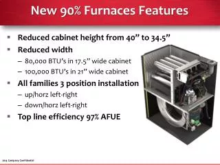
High-Efficiency Gas Furnaces 90 % plus • Draws in combustion air from outside thus reduces outdoor air infiltration (through windows, doors and walls) and room depressurization. • Have multiple heat exchangers. A primary just like a 80% or less furnace and a secondary that operates below the dew point temperature of the combustion gases and thus draws out the latent heat of the flue gases.
High-Efficiency Gas Furnaces 90 % plus • Flue gases flow from top to bottom in primary heat exchanger. • Then enter the secondary heat exchanger. Flue gases condense releasing latent heat. Secondary must be made of stainless steel and hi-temp plastic.
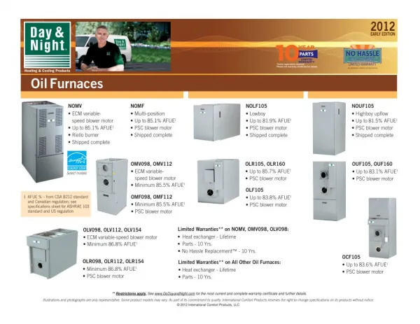
High-Efficiency Gas Furnaces (cont'd.) • Annual fuel utilization efficiency rating (AFUE) allows consumer to compare furnace performance before buying • Furnace efficiency ratings are determined by amount of heat transferred to the heated medium • Conventional furnace: 78-80% AFUE • Mid-efficiency furnace: 78-83% AFUE • High-efficiency furnace: 87-98% AFUE
Electronic Ignition Modules and Integrated Furnace Controllers • Control the ignition and sequence of operations in most modern gas furnaces • 100% shutoff system • Both pilot/main gas valve shut down in failure • Non-100% shutoff system • Main gas valve shuts down; pilot continues to bleed gas • Continuous retry with 100% shutoff • 90-sec trial for ignition
Electronic Ignition Modules and IFCs (cont'd.) • Lockout: time period to light or relight the pilot or main burner • Soft: semi-shutdown but module will keep trying to relight the system • Hard: full shutdown; module must be reset • Prepurge, interpurge, and post-purge periods allow blower motor to clear heat exchanger • IFC provides sequence schemes
Two-Stage Gas Furnaces • Use a two-stage gas valve and a two-speed draft inducer fan with two pressure switches • First stage puts out manifold pressure of 1.75 in. WC and operates at 50-70% of total heating output • Second stage puts out manifold pressure of 3.5 in. WC and 100% of total furnace output
Venting • In conventional gas furnaces • Use convection to vent flue gases but lose heat to prevent corrosive condensation • Use Type B vent; approved masonry materials • In high efficiency gas furnaces • Recirculate gases to retain heat • Use small fans and plastic pipe • Category specifies correct amount of excess air
Gas Piping • Observe all national and local codes • Piping size varies with furnace ratings and gas type • Should be steel, cast iron, plastic • Use pipe dope or Teflon tape on joints • Piping at furnace should provide for a drip tap, a shutoff valve, and a union • Assembly must be leak tested and purged
Combustion Efficiency • Incomplete combustion produces carbon monoxide • Enough secondary air must be provided to prevent this • Flames should be blue with orange tips • CO test gets information from flue gases needed to make air adjustments • Less secondary air means more CO
Summary Remember – You are mixing natural gas and electricity in a metal box in someone’s basement or garage. What could possibly go wrong???
For more information please contact Mark T. Weber, M.Ed., CMHE At North Seattle Community College WWW.NorthSeattle.edu Mark.weber@seattlecolleges.edu