Introduction to Scientific Visualization
570 likes | 966 Views
Introduction to Scientific Visualization. Materials from: Ken Flurchick Ohio Supercomputing Center Todd Veltman West Lyden High School Alan Shih, Dave Bock, Alan Craig, Polly Baker, Scott Lathrop, Lisa Bievenue, plus all the researchers who provided examples

Introduction to Scientific Visualization
E N D
Presentation Transcript
Introduction to Scientific Visualization Materials from: Ken Flurchick Ohio Supercomputing Center Todd Veltman West Lyden High School Alan Shih, Dave Bock, Alan Craig, Polly Baker, Scott Lathrop, Lisa Bievenue, plus all the researchers who provided examples National Center for Supercomputing ApplicationsUniversity of Illinois at Urbana-Champaign
Agenda • What is Visualization? • Why Do Visualization? • Why is Visualization Important? • The Visualization Process • Doing Visualization • Data Sources • Data Variables • Representation Types • Visualization Techniques • Interactive or Batch? • Data Types and Topologies
What is Scientific Visualization? • 1987 NSF Panel Initiative - Formal Definition • "Visualization is a method of computing. It transforms the symbolic into the geometric, enabling researchers to observe their simulations and computations. Visualization offers a method for seeing the unseen. It enriches the process of scientific discovery and fosters profound and unexpected insights.”
Early Representation • The Cave of Lascaux, France • ~15,000 years old • Tells a story • NOT visualization
Quantitative Representation • Tenth century • Inclinations of the planetary orbits as a function of time. • Oldest known attempt to show changing values graphically. Planetary Orbits
Computer Art and Scientific Visualization Cox, Donna; Patterson, Robert; Bargar, Robin; Daab, Fred; Moore, Michael; Moorman, Jan; Waegner, Chris; Erickson, Christian; Swing, Chris; Conrad, Renee; Knocke, Joel; Jordan, Robert; Brandys, Mike; Fossum, Barbara; Colby, Don; McNeil, Mike; Bajuk, Mark; Arrott, Matthew; Swanson, Amy Researchers Cerco, Carl; Noel, Mark; CEWES Visualizaiton Stein, Robert; Shih, Alan; NCSA Dr. Alan M. Shih
Visualization is a Form of Data Representation • Choice of appropriate representation
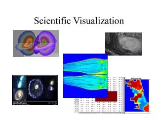
Why Do Scientific Visualization? • Visualization is the practice of mapping data to visual form • for exploration and analysis • for presentation • Goal of visualization • Leverage existing scientific methods by providing new scientific insight through visual methods.
Why is Visualization Important? • Computers brought about the ability to collect, create, and store more information • rise of computational science in mid-80s generated a firehose of data and the subsequent need for visualization • As a process of simulating a relevant subset of the laws of nature through a set of equations • Yields a set of numeric solutions -- Numbers, LOTS of them • May not be able to see, much less interpret, all of the results. Dr. Alan M. Shih
Visualization of Data • Try to envision the domain in your mind Dr. Alan M. Shih
Visualization of Data • But, with some modifications to the images... Dr. Alan M. Shih
Visualization of Data • Interpolated vs. Non-interpolated Dr. Alan M. Shih
Doing Visualization • Make Decisions Related to: • Data Sources • Data Variables • Representation Types • Visualization Techniques • Interactive or Batch? • Data Types and Topologies
Data Sources • Observation • wind tunnels, field observations, telescopes, space probes, water quality • Simulation • computational chemistry, fluid dynamics • Databases • protein data bank, genome studies
Data Variables • Scalar • temperature, pressure, velocity • Vector • magnetic field, speed • Tensor • stress, strain • Multivariate • weather characteristics, water quality factors
Scalar volume isocontour height field scatter plot image contour plot strip chart Vector ribbon particle traces arrow plot Data Representation Types • Tensor • disk and shaft ellipsoid • Multivariate • various glyph shapes
? What are some Visualization Techniques?
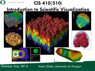
Visualization Techniques • 2D and 3D Plot/Graphs • Tables and Stacked Plots, Scatter plots • Contour Lines/Isosurfaces • Color Shading • Glyphs (Geometric Shapes) • Vector Fields • Arrows, Streamlines, Particle Tracing • Adding Textures • Volume Visualization • Animation • Data Sonification • Virtual Reality
Contours with Layers of Information Dr. Alan M. Shih
Composite Representation Dr. Alan M. Shih
Color Shading • Any graphics primitive (pixel, line, glyph, polygon...) can be assigned a color. • Adding color shading to represent a variable is a useful method of illustration. It is equivalent to adding an extra dimension to the visualization. • Requires appropriate choice of color map.
Representation Techniques • False Color • Height/Deformation Researchers Kovacic, David A., Romme, William H., Despain, Don G. Visualization Craig, Alan; NCSA, 1990 Researchers and visualization Haber, Bob; Lee, Hae-Sung; Koh, Hyun; NCSA, 1989 Dr. Alan M. Shih
Adding a Color Map • In the example, color values mapped to data values using linear interpolation.
Glyphs (geometric shapes) • A glyph is a simple shape used to represent a position in space. • Color and size of the glyph represent the data at that point. • The shapes can be spheres, cubes, tetrahedrons, arrows, boxes, ...
Glyph Example (Coal Combustion) • Spheres are used for glyphs. • Each glyph is a coal particle. • Size represents particle mass. • Color represents temperature.
Vector Fields - Arrows • Vector arrows are used to indicate both direction and magnitude at points in a vector field (e.g., velocity, magnetic fields) • Velocity Field for Flow Over a Blunt Fin example. • When used with a color map, up to three pieces of information can be represented by a vector arrow.
Normally associated with velocity fields Shows time-history of a massless particle Sometimes depicted as a twisted ribbon to show effect of rotation about streamline axis. Can also show movement of a glyph along the computed streamline. Vector Fields - Streamlines • More work, computational resources required to compute motion in a time-varying velocity field.
Representation Techniques • Particulate/ Trace • Iso-surfaces Researchers Wilhelmson, Robert; Brooks, Harold; Jewett, Brian; Shaw, Crystal; Wicker, Louis; Department of Atmospheric Science and NCSA Visualization Arrott, Matthew; Bajuk, Mark; Thingvold, Jeffrey; Yost, Jeffery; Bushell, Colleen; Brady, Dan; Patterson, Bob Produced by the Visualization Services and Development Group, NCSA Dr. Alan M. Shih
Textures • In addition to surface height, color and vectors one can use texture (bump mapping). • Bump map is a collection of bumps (texture) used to add additional information to a graphical primitive. • Interactive adjustment of parameters is desirable to obtain best results. • Careful use is needed as additions to an already rough surface can be distracting.
Texture Maps Texture Mapping Visualization Stein, Robert, Baker, Polly, NCSA, ongoing Sponsored by ARL Dr. Alan M. Shih
Contour Surface & Volume Visualization Dr. Alan M. Shih
Ray-Tracing is a common method for rendering large volumes. Different from surface rendering techniques. Tends to give more photo-realistic results. Also takes more computational resources. Volume Rendering
Time-varying phenomena are best visualized using animations. Can slow down events that happen too quickly for human perception. Animation is also useful for showing different perspectives of a static object (e.g., "fly-by"). Animations can be viewed on screen or can be recorded to video tape. Often need to save a large number of individual frames (images), then play them back quickly. Animation
Animation Damage Structure Researcher Namburu, Raju, CEWES Visualization Boch, David; Heiland, Randy; Baker, Polly; NCSA Stephens, Mike; CEWES
Static vs. Time-Varying Data • Static • At an particular instance of time • Particular Point of View, etc. • Time-Varying Animation • Evolving along the time line • Dynamic Data or Point of View
More Animations • Vector Animation • Volume Animation • Volume Animation (Layered Isosurfaces) • Volume Animation (Rotation) Dr. Alan M. Shih
Interactive or Batch? • Interactive Visualization • Allows the Ability to Control in Real-Time • Limits the Amount of Data to Be Visualized. • Useful for Analysis and Exploration • Batch Visualization • High-Quality, Complex Representation • No Control in Real Time. • Useful for Presentation, Communication, high complexity
Data Types • Topology • structure, connectivity • Geometry • shape • Variables • temperature, pressure, velocity • Metadata • information about data, e.g., initial conditions, data of observation
Data Topologies • Data can be • structured (e.g., gridded data) • unstructured (e.g., finite element data) • a combination of both. • Data can have different dimensions, both spatial and computational.
Most data representing physical phenomena are sampled at discrete points on a grid or mesh. Data on grids that can be mapped into one or more rectangles/boxes is called structured data. Data Topologies • Structured meshes can be uniform, rectilinear, or irregular. • Grid point, i,j , is identified by the intersection of grid line, i, and grid line, j.