Download
1 / 15
150 likes | 443 Views
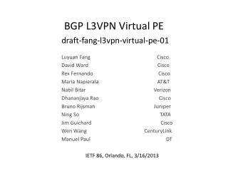
BGP L3VPN Virtual PE draft-fang-l3vpn-virtual- pe-01. Luyuan Fang Cisco David Ward Cisco Rex Fernando Cisco

E N D
BGP L3VPN Virtual PEdraft-fang-l3vpn-virtual-pe-01 Luyuan Fang Cisco David Ward Cisco Rex Fernando Cisco Maria Napierala AT&T Nabil Bitar Verizon DhananjayaRao Cisco Bruno Rijsman Juniper Ning So TATA Jim Guichard Cisco Wen Wang CenturyLink Manuel Paul DT IETF 86, Orlando, FL, 3/16/2013
Motivation • Extend BGP IP VPNs [RFC 4364] into Cloud/DC/Mobile environment as part of the network virtualization effort. • Why? Leverage the SP strength on l3vpn in building virtual private cloud • L3VPN is the most deployed SP provisioned VPN • It has been proven to scale • Provide end-to-end native l3vpn connectivity to distinguish from Internet overlay • Reality check • 11/2011 IETF 82, Taipei: VPN4DC was requested/supported by many SPs with large L3VPN deployment • Today: Many SPs said I’d like to have it deployed “yesterday”
Virtual PE Definition • A virtual PE (vPE): a BGP IP VPN PE software instance which may reside in any network or computing devices. • vPE-F: vPE Forwarding Plane • vPE-C: vPE Control Plane • vPE-C and vPE-F can be decoupled, they may reside in the same physical device, or most often in different physical devices.
vPE Architecture Reference Models (1) vPE-F in the end device, vPE-C in the controller MPLS Core Virtual RR (vRR) WAN edge Gateway Controller /Orchestration vPE-F Application/VM (CE)
vPE Architecture Reference Models (2) vPE in the end device, using MP-BGP for control MPLS Core Virtual RR (vRR) WAN edge Gateway MP-BGP vPE Application/VM (CE)
vPE Architecture Reference Models (3) vPE in the ToR, using MP-BGP for control MPLS Core Virtual RR (vRR) WAN edge Gateway MP-BGP vPE Application/VM (CE)
vPE(-F) on a Server vPE and VM relationship -> PE-CE - vPE – L3 SW instance on server - vPE and VM relationship: PE-CE - VRF on vPE to isolate individual tenant routing and traffic separation vPE(-F) VRF R VRF Y VRF G VM VM VM VM VM CE CE CE CE CE Server
End-to-end L3VPN Overlay from Enterprise to SP DC with vPE in End Device Forwarding: IP, MPLS, others Controller /Orchestration MP-BGP RR RR Enterprise G VM VM VM VM VM VM VM VM VM VM VM VM VM VM VM VM VM VM VM VM VM VM VM VM MP-BGP RR CE VRF VRF VRF VRF VRF VRF VRF VRF VRF VRF VRF VRF VRF VRF VRF VRF VRF VRF VRF VRF VRF Host Host Host Host Host Host Host VRF VRF vRR PE PE vRR Provider Networks P Enterprise R DC VRF VRF VRF Not VPN aware DC infra – Not VPN aware vPE CE DC Gateway Server VRF VRF PE PE Gateway to vPE signaling options: 1) Through Controller 2) MP-BGP Enterprise Network/DC Provider Network Provider DC
Control Plane 1. SDN Controller approach • vPE control plane and data plane are physically decoupled. The control plane directing the data flow may reside elsewhere, such a centralized controller. • The controller can be used for routing information distribution / directly insert the entries into FIB. 2. Distributed MP-BGP control plane • vPE participates in overlay BGP IP VPN control protocol: MP-BGP [RFC4364]. 3. vPE-C can be anywhere 4. Use RR and RT Constrain [RFC4684] to scale.
Data Plane 1. The VPN forwarder location options: 1) within the end device where the CE (e.g., application/VMs) are. 2) in an external device which the end device connect to, for example, a Top of the Rack (ToR) in a data center. 2. Considerations in design: • Device capability • Overall solution economics • QoS/firewall/NAT placement • Optimal forwarding • Latency and performance • Operational impact 3. Encapsulation • MPLS • IP / GRE tunnel [RFC4023], [RFC4797] • Other IP network overlay encapsulations e.g. VXLAN, NVGRE.
Management/Orchestration The orchestration system 1) MUST support IP VPN service activation in virtualized Data Center. 2) SHOULD support automated cross provisioning accounting correlation between WAN IP VPN and Data Center for the same tenant. 3) MAY support automated cross provisioning state correlation between WAN IP VPN and Data Center for the same tenant
vPE Push Model • Top down approach - push IP VPN provisioning from management/orchestration systems to the IP VPN network elements. • Common model in SP IP VPN enterprise deployment. • When extending existing WAN IP VPN solution into the a Data Center, it SHOULDsupport off-line accounting correlation between the WAN IP VPN and the cloud/DC IP VPN for the tenant, the systems SHOULD be able to bind interface accounting to particular tenant. It MAY requires offline state correlation as well, for example, bind interface state to tenant.
vPE Pull Model • Bottom-up approach - pull from network elements to network management/AAA based upon data plane or control plane activity. • Common model used in broadband deployment. • Dynamic accounting correlation and dynamic state correlation are supported. For example, session based accounting implicitly includes tenant context state correlation, as well as session based state which implicitly includes tenant context.
Next Steps • Address all comments on the list and in the meeting • Submit a new version • Ask the WG to check interest for adopting this work as WG item