Download
1 / 70
710 likes | 823 Views
Workshop presentation on representing main beams in non-regular arrays for antenna calibration, focusing on mutual coupling effects and sparse polynomial methods. Specific to SKA AAlo telescope stations. Analysis includes effective area, interference suppression, and array factorization. Workshop covers Zernike series, Fourier-Bessel representation, and corrects for mutual coupling effects using multiple-mode approaches. Other topics include aperture sampling, scanning, and accurate pattern representation.

E N D
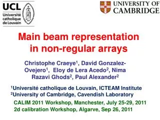
Main beam representation in non-regular arrays Christophe Craeye1, David Gonzalez-Ovejero1, Eloy de Lera Acedo2, NimaRazavi Ghods2, Paul Alexander2 1Université catholique de Louvain, ICTEAM Institute 2University of Cambridge, Cavendish Laboratory CALIM 2011 Workshop, Manchester, July 25-29, 2011 2d calibration Workshop, Algarve, Sep 26, 2011
2 parts Preliminary: Patterns of apertures – a review Next: analysis of aperture arrays with mutual coupling Algarve meeting, 2011
a b r Algarve meeting, 2011
Fourier-Bessel series Algarve meeting, 2011
Zernike series NB: the Zernike function is a special case of the Jacobi Function Algarve meeting, 2011
Zernike functions Picture from Wikipedia CALIM 2011
Radiation pattern Hankel transform Algarve meeting, 2011
F.T. of Bessel Algarve meeting, 2011
FT of Zernike Algarve meeting, 2011
Sparse polynomial Algarve meeting, 2011
Context: SKA AA-lo Non-regular: max effective area with min nb. elts w/o grating lobes. CALIM 2011
Problem statement Goal: pattern representation for all modes of operation at station level. Too many antennas vs. number of calibration sources Calibrate the main beam and first few sidelobes Suppress far unwanted sources using interferometric methods (open). Compact representations of patterns, inspired from radiation from apertures, including effects of mutual coupling Algarve meeting, 2011
Specific to SKA AAlo • Fairly circular stations (hexagonal would be OK) • Relatively dense • Weak amplitude tapering – some space tapering • Irregular => all EEP’s very different • Even positions are not 100 % reliable (within a few cm) • Correlation matrix not available • Nb. of beam coefficients << nb. Antennas • Restrict to main beam and first few sidelobes • Even assuming identical EEP’s and find 1 amplitude coefficient per antenna is way too many coefficients Algarve meeting, 2011
Outline Limits of traditional coupling correction Array factorization Array factors: series representations Reduction through projection Scanning Algarve meeting, 2011
Embedded element pattern Z L Impedance isolated elt Array impedance matrix To get voltages in uncoupled case: multiply voltage vector to the left by matrix CALIM 2011
Embedded element pattern Z L After correction, we are back to original problem, with (zoomable, shiftable) array factor Gupta, I., and A. Ksienski (1983), Effect of mutual coupling on the performance of adaptive arrays, IEEE Trans. Antennas Propag., 31(5), 785–791. CALIM 2011
Mutual coupling correction Half-wave dipole Isolated Embedded Corrected CALIM 2011
Mutual coupling correction Bowtie antenna l=1.2 m, l=3.5 m Isolated Embedded Corrected CALIM 2011
Mutual coupling correction Bowtie antenna l=1.2 m, l=1.5 m Isolated Embedded Corrected SINGLE MODE assumption not valid for l < l/2 ~ CALIM 2011
Multiple-mode approach Macro Basis Functions(Suter & Mosig, MOTL, 2000, cf. also Vecchi, Mittra, Maaskant,…) a + b + g + d MBF 2 MBF 4 MBF 1 MBF 3 CALIM 2011
C111 C211 C311 MBF 1 C122 C222 C322 MBF 2 Array factorisation Z L s n Antenna index Coefficients for IDENTICAL current distribution … CALIM 2011
C111 C211 C311 MBF 1 C122 C222 C322 MBF 2 Array factorisation Z L s n Antenna index Coefficients for IDENTICAL current distribution … CALIM 2011
Example array - Array radius = 30λ0. - Number of elements = 1000. λ0 - Distance to ground plane = λ0/4. - No dielectric. λ0 Z = 200Ω CALIM 2011
Random arrangement Random configuration ~ 35 dB E-plane H-plane CALIM 2011
Quasi-random arrangement CALIM 2011
Radius of Influence 100 elements 1000 elements 10 elements H-plane ICEAA 2011
Aperture sampling (1) CALIM 2011
Aperture sampling (2) Define a local density (several definitions possible) CALIM 2011
Aperture scanning (1) CALIM 2011
Aperture scanning (2) CALIM 2011
Patterns versus size of array CALIM 2011
Coherent & incoherent regimes ~ ~ 0.3 Number of sidelobes in “coherent” regime CALIM 2011
Aperture field representation a b CALIM 2011
Pattern representation Angle from broadside CALIM 2011
Polynomial decomposition CALIM 2011
Fourier-Bessel decomposition = CALIM 2011
Fourier-Bessel decomposition = A. Aghasi, H. Amindavar, E.L. Miller and J. Rashed-Mohassel, “Flat-top footprint pattern synthesis through the design of arbitrarily planar-shaped apertures,” IEEE Trans. Antennas Propagat., Vol. 58, no.8, pp. 2539-2551, Aug. 2010. CALIM 2011
Zernike-Bessel decomposition Y. Rahmat-Samii and V. Galindo-Israel, “Shaped reflector antenna analysis using the Jacobi-Bessel series,” IEEE Trans. Antennas Propagat., Vol. 28, no.4, pp. 425-435, Jul. 1980. CALIM 2011
Array factor with apodization CALIM 2011
Array factor with apodization CALIM 2011
Apodization function w(r) extracted CALIM 2011
Approximate array factor extracted 20 % error on amplitudes l/4 error on positions (at 300 MHz) CALIM 2011
Residual error with Z-B approach CALIM 2011
Residual error with Z-B approach CALIM 2011
Residual error with Z-B approach CALIM 2011
Residual error with Z-B approach CALIM 2011
Residual error with Z-B approach CALIM 2011
Residual error with Z-B approach CALIM 2011
Residual error with Z-B approach CALIM 2011