Download
1 / 26
260 likes | 437 Views
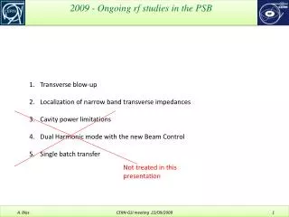
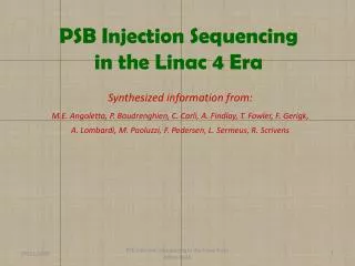
Summary of discussions held with: M.E. Angoletta, P. Baudrenghien, C . Carli , A. Findlay, G. Hagmann, I. Kozsar, B. Mikulec, J. Molendijk, M. Paoluzzi, J-L Sanchez, R. Scrivens , S. Zorzetti. PSB with Linac 4 - RF matching. Introduction: the Linac 4 chain. 2 μ s. Pre-chopper

E N D
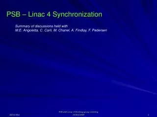
Summary of discussions held with: M.E. Angoletta, P. Baudrenghien, C. Carli, A. Findlay, G. Hagmann, I. Kozsar, B. Mikulec, J. Molendijk, M. Paoluzzi, J-L Sanchez, R. Scrivens, S. Zorzetti PSB with Linac 4 - RF matching PSB-LIU meeting 24/04/2013
Introduction: the Linac 4 chain 2μs Pre-chopper +LEBT Debuncher RF Feedforward Distri 4*rf 180 m Source 45 keV Chopper Amplitude modulated for energy modulation (painting) Courtesy F. Gerigk PSB-LIU meeting 24/04/2013
Our goal is to inject the Linac 4 beam (160 MeV) into PSB rf buckets – and not outside! Injection in the PSB – Chopping and Painting • The PSB rf buckets, h1 or h2, • will be filled up by acting on: • the L4 energy (160 MeV +/- 1.25 MeV) • the L4 beam chopping( at 3 MeV) Courtesy C. Carli Chopper and PSB RF need to be “in-phase” during injection! Both entities will be synchronized to a single external reference clock The energy modulation needs to be in-phase with the different ring injections PSB-LIU meeting 24/04/2013
Injection in the PSB – B-Field increase As soon as the injection starts in one ring, the rf system will decouple itself from the injection reference and follow a frequency program corresponding to the B-field increase (1.2 Gauss/100us) -> accelerating buckets Courtesy C. Carli The maximum phase advance between reference clock and RF signal following and accelerating program (ΔR = 0 ) is 7.2 deg of the revolution after 100 turns. The injection field can be made equal for each injection in each ring with BDLs RF and injection reference clock have a predictable phase relation during the filling phase PSB-LIU meeting 24/04/2013
Injection in the PSB – Ring change The switching from one ring to another should occur when the bucket filling is completed. => The distributor should take into account the revolution phase Courtesy C. Carli The distributor will be switched synchronously with the injection rf = injection reference + predictable phase PSB-LIU meeting 24/04/2013
Linac 4 during Chopping 2μs Pre-chopper +LEBT Debuncher RF Feedforward Distri 4*rf 180 m Source 45 keV Chopper Amplitude modulated for energy modulation (painting) Courtesy F. Gerigk • Start injection pulse -> • Launch pre-calculated chopping sequence -> send associated feed-forward to cavities • Launch modulation program on PIMs -> adapt phase of debuncher accordingly. PSB-LIU meeting 24/04/2013
Debuncher Pre-chopper +LEBT Energy modulation Source Distri Chopper RF R4 Linac 4 Synchronisation of PSB with L4 RF R3 180 m RF R2 Linacrf feed-forward RF R1 45 keV Modulation program Voltage modulation Energy modulation Control OP Control Phase modulation BIXi.SINJ_MODULATOR BIXi.SDIS CO Timing Chopper Control (ring by ring) BIXi.SInjChop BIXi.SInjRF REV REFERENCE Inj. Ref Clock h2 1/2 h1 SP2T Inj. rf reference (h1 or h2) BIXi.SDIS (Number of turns) Chopping table OP Control BIi.RF_PHASE BIi.FRED_PROG PSB-LIU meeting 24/04/2013
RING Blanking: this is a reaction to so-called “external conditions” treated by the MTG • The external conditions are triggered by: • faults detected on PSB extraction elements (kickers, septa, recombination bendings) • A stop-beam request from an experiment • After a response time taking up to two cycles (the MTG considers the next cycle, so it doesn’t change it when it has been defined), and depending on the external conditions, different actions can be triggered (switching to a spare cycle if compatible, 0-turn imposed by timing means (on the distributor, RF-S_INJ pulse of each ring...) • This Ring Blanking is aimed at being kept in place although the 0-turn now has more consequences ( Magnetic compensation no more valid in the PSB, possible monitoring errors in the Linac 4 chain…) Ring Blanking PSB-LIU meeting 24/04/2013
Ring Blanking Comments: The energy modulation function has been depicted with a ring-by-ring framing to allow the usage of ring-blanking. In order to avoid unacceptable energy transients at the PIMs stage when making a ring blanking, one possibility would be to impose a determined value to be set both at the beginning and at the end of each ring injection -> unpractical! Another approach, offering a wider range of painting possibilities would be to allow for up to 20 us (full sweep of the modulator) of no-beam time at the beginning of an injection, in order for the modulator to settle to any requested energy starting from any other. This approach would require 60 more us in the distributor’s PFN. (According to Luc Sermeus we should have 600 us, which is sufficient) N.B.: A decrease of the Linac 4 intensity would also imply a lengthening of the PFNs for the same final maximum PSB intensity. The chopper receives one start for each ring; the table doesn’t thus need to integrate the phase drifts w.r.t. the reference along the previous injection (accelerating buckets). At this level a ring blanking (switching to the next ring without redefining the table) is also possible! PSB-LIU meeting 24/04/2013
RING INHIBIT: real time action aimed at both stopping the beam at the chopper level (3 MeV) and inhibiting its acceleration at the PSB LL-RF stage. This inhibit can occur anytime during or before injection, when a relevant rf fault has been detected in a given ring. This inhibit (4 signals, one per ring) will be received both at the chopper-control stage and at the low-level rf stage from the “RF Interlock Interface”. A specific ring inhibit concerning only the LL-RF will be triggered when a detected (real-time) “beam over-current” is measured. During a ring inhibit all machine parameters remain identical; there is no timing change. Ring Inhibit PSB-LIU meeting 24/04/2013
Interlock interface Courtesy S. Zorzetti PSB-LIU meeting 24/04/2013
In terms of longitudinal relative emittance growth, the worst case would occur when the 3 first rings (4, 3, 2) are programmed with 100 turns (highest possible intensity) and the last one (R1) with 1/20th of a turn (LHC high intensity single bunch where the longitudinal emittance should be preserved). When the 3 first rings are blanked, The beam will reach directly R1 at the beginning of the cycle, when the ramping field will have a value 3.6 Gauss lower than expected (Bdot = 1.2 Gauss/100us) => dB/B = 3.6/2311 = 1.5 E-3 For this field lower than expected, on the first turn the orbit will be longer, the revolution period bigger and the revolution frequency smaller. The rf bucket will thus appear higher in energy. The beam will have thus a – 80 keV energy error with respect to the rf bucket (see next slide). With a 120 keV energy spread (+/- 1 sigma) linac beam, this error would roughly double its emittance (rule of thumb) after filamentation. But this will never occur as the phase loop will enter into action after 1 us and damp the motion in the phase space with a time constant of 50 us (much faster than the synchrotron motion having a period Ts ≈ few ms. Effect of a ring blanking on beam parameters PSB-LIU meeting 24/04/2013
Energy error with 3.6 Gauss error at PSB injection PSB-LIU meeting 24/04/2013
Radial error with 3.6 Gauss error at PSB injection The initial orbit error due to a field error would also induce a betatron motion that would increase the horizontal emittance after filamentation. The relative emittance growth can be estimated using the value of the L4 beam emittance (value to be collected) The effect of this injection error can be cancelled with a transverse damper if its damping time constant is smaller than the filamentation time (value to be collected). With the upgraded TFB system and its increase power (800 W per kicker plate instead of 100 W) it is likely that this radial error will not be a concern. PSB-LIU meeting 24/04/2013
L4 to PSB synchronization issues seem to be solved with the proposed setup. Prior to injection the rf bucket of the 4 rings will be synchronized to an external Reference clock. The same reference clock will be used to trigger the chopper, the energy modulation and the distributor. Ring blanking and inhibit can be activated without perturbing the other rings. In order to use the painting function with flexibility, a 20 us period with no beam should be allowed before injection. The minimum Chopper beam-ON time (15 ns) means a minimum beam intensity of 6E9 ppb (linac beam = 65 ma or 4E8 p/ns), with 3.3% precision. LHC probe = 5E9 ppb Max 2 ON-OFF periods during one revolution means no fancy chopping on h2. Distributor rise-time + overshoot ≈ 2 us at present stage ~(1 us specified) => not a practical issue! Need for an accelerating bucket at injection to be assessed (some complexity on the rf side). Painting an accelerating bucket into a stationnary bucket seems sufficient at first glance) Conclusion PSB-LIU meeting 24/04/2013
Additional slides PSB-LIU meeting 24/04/2013
Our Quantum: • the L4 bunch • 1.15 * 109 protons (65mA) • TRF = 2.84 ns • DE = 120 keV (+/-1s => 68 % of the beam ) L4 beam in the PSB + 1 MeV To be confirmed +/- 1 MeV = Aperture of the L4 transfer line (max bucket height = +/-1.25 MeV) - 1 MeV 65 mA in Linac 4 => 4 E11 p / us Energy modulation slew-rate (last 2 PIM cells): 124 keV/ms (124 keV / turn ≈ Linac 4 energy spread at +/-1σ). PSB-LIU meeting 24/04/2013
L4 Source and Pre-Chopper + LEBTRef: R. Scrivens Present Source current = 10 -> 18 mA < 65 mA specified before chopper => 40 mA after chopping PSB-LIU meeting 24/04/2013
ChopperRef: M. Paoluzzi Rise time: 10 -> 90 % ! Burst length < 500 us Burst repetition rate < 2 Hz In-out chopper delay variation < 0.5 ns = 2E8 p ( affects beam On and OFF durations) The bunch length at this location is 280 ps within an rf period of 2’839ps => inter-bunch spacing = 2.56 ns max 2 times: beam ON – Beam OFF in one revolution ! (Just enough for an injection on h2) PSB-LIU meeting 24/04/2013
During beam segment, RF feedbacks and all feed-forwards (for power supply ripple, chopping sequence, beam intensity) are active and specifications should be met L4 Cavities (DTL, CCDTL, PIMS, De-Buncher)Ref: P. Baudrenghien PSB-LIU meeting 24/04/2013
L4 PIMSRef: P. Baudrenghien Fastest sweeping rate with 40 mA average current Possible issue: 1 ring with 1 bucket to be filled-up entirely in 1 sweep means you have not the same initial energy when filling the following ring… except if you wait 20 us… PSB-LIU meeting 24/04/2013
PSB DistributorRef: L. SERMEUS At present: Rise time + overshoot ≈ 2 us > requested 1 us 1 us response time seems very challenging for the designers!! PSB-LIU meeting 24/04/2013
PSB injection practical values PSB-LIU meeting 24/04/2013
The foreseen PSB Beam Control is activated at the pace of a 200 kHz clock (every 5μs). This interrupt clock or “fast-loop-clock” is asynchronous w.r.t. the injection process. • The rf doesn’t change in between 2 “fast-loop-clock” tics - period corresponding to 5 injected turns. • For a perfect tracking of the rf frequency change, the “fast-loop-clock” should be in phase with the injection process. Evolution of the rf bucket phase during injection • The frequency increase (ΔR =0) during injection creates a parabolic revolution phase deviation from the initial reference of 6.82o after 100turns (1.7o after 50 turns) and cannot be ignored. • The phase error caused by the step-by-step frequency program compared with the linear increase is < 54 mo and can be thus ignored. • The phase error due to the 5μs jitter in the DSP generated frequency program < 1.33o after 100 turns (acceptable) Averaged Frequency Frequency Updated every 5 μs • 379 Hz 100 μs PSB-LIU meeting 24/04/2013
Injection at a fixed frequency (100 turns injected) Ramping-up actually slower than shown PSB-LIU meeting 24/04/2013
Injection in an accelerating bucket (100 turns injected) Ramping-up actually slower than shown PSB-LIU meeting 24/04/2013