Download
1 / 35
350 likes | 500 Views
Development of two-dimensional gaseous detector for energy-selective radiography. Introduction GEM Application to Neutron Detector Detector system Performance studies with pulse neutron beam Basic test Energy selective neutron radiography Summary. Shoji Uno (KEK-DTP)

E N D
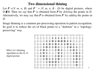
Development of two-dimensional gaseous detectorfor energy-selective radiography • Introduction • GEM • Application to Neutron Detector • Detector system • Performance studies with pulse neutron beam • Basic test • Energy selective neutron radiography • Summary Shoji Uno (KEK-DTP) TIPP2011Chicago, USA June 10, 2011
GEM (Gas Electron Multiplier) Double side flexible printed circuit board Electric field Hole diameter70mm Hole pitch140mm Thickness50mm Cu thickness5mm • Developed by F.Sauli (CERN) in 1997. • NIMA 386(1997)531
Application to Neutron Detector • Expensive 3He Gas is not necessary. • No pressure vessel • Free readout pattern • High resolution • Position and Time • Insensitive against g-ray • Capability against high counting rate Ar-CO2 Cathode plate With B10 B10 coated GEMs Normal GEM Readout board
Chamber structure Ar/CO2 = 70:30 Thickness of Boron-10 : 4.4mm 2.0mm + 0.6mm ×4 8 mm Al - 10B cathode ED = 1.5 kV/cm 1 mm ( 0.5mm ) 150V (75V) B GEM 1 240V 1 mm ET = 1.5 kV/cm 150V B GEM 2 240V 1 mm ET = 1.5 kV/cm 150V GEM 1 400V ET = 2.2 kV/cm 2 mm 440V GEM 2 370V EI = 4.0kV/cm 2 mm 800V X(120) +Y (120) strips 0.8mm pitch Readout strip
Block diagram for readout board Readout board Detector signal Sampler 100MHz Digital signal Noise Filter 256 FE2009 ASIC 256 x8 Hit Pattern・Data TCP/IPProtocol without CPU Coincidence Logic SiTCP Data Format Ethernet Coincidence・Data Time 10nsec unit Threshold Control
I/F One HV cable Three LV cables One Ethernet cable Electronics 8 ASIC chips + 1 FPGA FE2009 ASIC : KEK-DTP Data transfer and Control through Ethernet SiTCP by T. Uchida(KEK) Using Note-PC Present Detector System Ethernet Electronics Low Voltage GEM Chamber Compact and Portable System T.Uchida et. al., "Prototype of a Compact Imaging System for GEMdetectors," was published on IEEE TNS 55(2008)2698.
Several test experiments at the pulsed neutron sources in J–PARC MLF (BL21, BL10), Hokkaido Universityand RAL ISIS (ROTAX)
Experimental setup Cut view of BL21 Vacuum duct Sample position Vacuum duct GEM GEM Neutron beam Neutron beam Neutron beam Vacuum duct Collimator Unit: mm Get lost pipe Shield A neutron irradiation test was performed at BL21 in MLF of J-PARC. The Plateau curve as a function of supplied high voltage 10
Data samples The beam profile and its TOF distribution L = 18789 mm ~ 18.8 m L: distance from the source to the detector An image of a cadmium slit and its TOF distribution (Å) L = 18789 mm 27 mm Events from 1.5 Å to 8 Å are selected 60 mm Cd cutoff The thickness of the slit ~0.5 mm This image is produced with a wavelength cut. (Å) Our system can obtain a 2D image and its TOF at the same time. 11
Position resolution at ROTAX in ISIS of RAL Pin-hole 0.5mmf FWHM(H) 1.1mm(1.4pixel) FWHM(V) 1.1mm(1.3pixel)
Capability to reject gamma ray Gamma ray can be rejected further using pulse width (pulse height) information, if necessary. at BL21 in J-PARC Gamma ray
Energy Selective Neutron Radiography Resonance absorption region(E>1eV) Bragg Edge region (Thermal and cold)
Resonance absorption imaging By T. Kai (JAEA) et al. at BL10 in J-PARC
One more demonstration TEST Sample Ratio of ToF spectrums with/without sample EURO coin gold coin Imaging data with around 450msec ToF
Energy Selective Neutron Radiography Resonance absorption region(E>1eV) Bragg Edge region (Thermal and cold)
Extinction function for microstructure H.Sato of Hokkaido University Sabine function Primary extinction (re-diffraction) inside a crystallite (a mosaic block) Bragg component Laue component Non re-diffracted neutron Crystallite Re-diffracted neutron Diffracted neutron : Refinement parameter Incident beam Transmission beam a-Fe (BCC) simulation calculation Grain S = 1 mm Whole intensity correction ! w/o extinction S = 5 mm Visualized microstructure parameter S : Crystallite size along the beam direction S = 10 mm 6
Without sample With sample Nb plate with weldingat ROTAX With sample Without sample Number of events Number of events
Bragg edge at welding region Normalized intensity (I/I0) Normalized intensity (I/I0) Normalized intensity (I/I0) Normalized intensity (I/I0) at Brag edge
Imaging for bended iron platesat LINAC in Hokkaido University Sample 90°Bending and Re-flattening 90°Bend 60°Bend +Reference (without bending) 30°Bend Moderator Sample Flight tube 504cm 70cm 100cm GEM Detector 674cm
Results 90° Bending 60° Bending 30° Bending Reference Re-flattening Position Y (mm) Photo of iron plates Position X (mm) Two dimensional imaging of crystallite size in the bended iron plates can be done clearly. Visualization of microstructure for heavy material can be performed with the gaseous neutron detector.
Summary • Neutron detector with Boron coated GEM was constructed. • Boron converter • Gas amplification at GEM • Two-dimensional readout with X-Y strips • High speed compact readout system • Test experiments were performed at several pulsed neutron sources. • Good position resolution without distortion • Two dimensional position and flight time can be obtained simultaneously. • Gamma ray can be rejected further using the pulse width (pulse height). • Good performance for the energy selective radiography is demonstrated.
Thickness of Boron and Number of B-GEM foils Using 252Cf radiation source Number of Neutrons ▲ 0.6mmt ● 1.2mmt Number of sheets of B-GEM Higher efficiency could be obtained for more B-GEM foils. Saturation was observed in thicker Boron layer.
Chamber Structure for Beam Test Boron coated Aluminum Foil 1.2mm Gas: Ar-CO2(70/30) ED=1.5kV/cm DVGEM=220V(B-GEM) ET=1.5kV/cm(B-GEM) DVGEM=560V(100mmGEM) EI=6.3kV/cm 4 Boron coated GEM foils 1.4mm 100mm thick GEM 2.0mm 0.8mm pitch X-Y strips 120+120 Thickness of Boron Layer : 1.2mm In total1.2mmx9=10.8mm
Detection Efficiency • 1mmφ Pin Hole • 3He Counter with 1inch 10atm • 61405 counts/100sec • Boron-GEMFoil • 18599 counts/100sec • Detection Efficiency • 30% at 2.2Å • with 4 GEM foils • Boron-10 : 1.2mmt 2.4mmt per one GEM foil
10mm Cd Slit Two Dimensional Image 96mm 96mm
Position Resolution 0.5mmφ Pine Hole FWHM =1.3mm
Sample test Large anglescattering Single NaCl Small angle scattering Hypresica (SiO2) Neutron Sample HPS 500nm Direct Beam HPS 200nm Background
Position resolution Data with a B4C slit Beam profile data Divided data 104 mm 104 mm The B4C slit (35 mm 35 mm) was put in front of the GEM. To compensate the beam profile, the data with the slit is divided by the beam profile data. The projection data Z 35 mm 35 mm In the histogram of the slope (=DZ/DX), a sharp peak appears on the edge of the B4C slit. In order to estimate position resolution, the sharp peak is fitted by a gauss function. The position resolution; ~1.3 mm (FWHM) The correction of the beam divergence is not performed yet. X The slope data (=DZ/DX) DZ/DX Constant: 0.26 Mean: 32.85 Sigma: 0.56 X TIPP09 Mar. 14 2009 @Tsukuba, Japan DZ/DX is obtained by subtracting the one from the adjacent one. 15
Uniformity (Neutron sensitivity, Imaging) Data with a Cd slit Beam profile data Divided data 1 mmf, 4.8 mm pitch The projection data A cadmium slit (1 mmf, 4.8 mm pitch) was put in front of the GEM. To compensate the beam profile, the data with the slit is divided by the beam profile data. The thickness of the slit ~0.5 mm the projection data is fitted by a gauss function. To estimate the uniformity of the neutron sensitivity, the peak area is used. The peak area: 1.73 0.30 (3s) To estimate the distortion of the 2D image, the distance between the peaks is used. The distance between the peaks: 4.88 0.10 mm Fill the peak area Fill the distance between two peaks The dispersion of the neutron sensitivity is estimated at within 17%. The distortion of the 2D image is very small. TIPP09 Mar. 14 2009 @Tsukuba, Japan 16
10cm 10cm GEM Foil&Test Chamber Scienergy Co., Ltd. (Japanese company) Boron coated GEM Enriched B-10 Purity > 99% Standard GEM Foil without Boron coating Hole diameter70mm Hole pitch140mm Thickness50mm Cu thickness5mm
2 Simulation study No. of GEM foils Thickness of 10B (mm) Se-Hwan Park et. al., IEEE NS52(2005)1689 CASCADE M. Klein ~35%X0.77 = ~27% ~32%X0.77= ~25% 0.77 : Fraction of Cu surface on GEM
100 mm Gas (1 mm) - sensitive area thermal neutron 100 mm Al (0.5 mm) 10 B layer Gas (20 mm) Al (0.05 mm) Principle of neutron detection n(10B,a)7Li reaction Neutrons are detected by n(10B,a)7Li reaction. In order to optimize our detector design, we performed a GEANT4-based simulation. The GEANT4-based simulation - 1.8 Å thermal neutrons shot into the detector at the normal incident. - An event depositing energy in the gas is defined as a hit. The neutron sensitivity as a function of 10B thickness - The neutron sensitivity reaches its maximum around 3 mm. - Over the thickness, charged particles (a or 7Li) can’t enter into the gas volume. Approximately 0.1% neutron sensitivity is achieved by a 0.02 mm 10B layer. A schematic view of the Geant4-based simulation (6%) (94%) TIPP09 Mar. 14 2009 @Tsukuba, Japan 5
30th row 40th row 50th row 60th row Transmission Spectrum for Bended Iron 90º bended iron Reference(40th row) 90°bend Neutron Transmission 30th 60th row TOF(μsec) Shapes of Bragg-edge are analyzed in a RITS code, which is developed by H. Sato. Crystallite size bin by bin