Download
1 / 16
180 likes | 360 Views
Vision for Mechanistic Concrete Crosstie and Fastener System Design. International Concrete Crosstie and Fastening System Symposium 8 June 2012 Urbana, IL. J. Riley Edwards, Brandon J. Van Dyk, and Marcus S. Dersch. Outline. Mechanistic Design Definition Other Applications Process

E N D
Vision for Mechanistic Concrete Crosstie and Fastener System Design International Concrete Crosstie and Fastening System Symposium 8 June 2012 Urbana, IL J. Riley Edwards, Brandon J. Van Dyk, and Marcus S. Dersch
Outline • Mechanistic Design • Definition • Other Applications • Process • Objectives • Path Forward • Data Collection and Analysis • Implementation • Questions and Comments
Current Design Process • Mostly iterative, with focus on reduction of LCC reduction of the crosstie and fastening system • Loading “conditions” empirically derived • Some loading conditions extrapolated (AREMA C-30, Table 30-4-4) • Process can be driven by production and installation considerations • Option for Improvement Mechanistic Design
Highway Example of Mechanistic Design • MEPDG – Mechanistic-Empirical Pavement Design Guide • Inputs – geometry, traffic, climate, materials • Output – pavement responses to load, compute distresses and loss of ridability • Apply to the rail industry?
What Is Mechanistic Design? • Analytical approach not an iterative design process • Uses loading data to develop a design that functions under expected loading conditions • Requires design for specific failures modes or performance indicators • e.g. RSD, center cracking, post insulator wear, etc. • Inputs – Crosstie and fastening system component geometry, traffic (axle load and tonnage), climate, materials • Outputs – Tie and fastening system responses (stresses/strains) to loads, performance characteristics, wear rates?
Mechanistic Design Process • Quantify System Input Loads (Wheel Impact Load Data (WILD), Instrumented Wheel Sets (IWS)) • Qualitatively Establish Load Path (Free Body Diagrams, Basic Modeling, etc.) • Establish the locations for load transfer, in need of further analysis and study • Quantify Loading Conditions at each Interface / Component (Including displacements) • Laboratory and Field Experimentation • Analytical Modeling (Basic FEM) • Link Quantitative Data to Component Geometry and Materials Properties • Go / No-Go Materials Decision
Mechanistic Design Process (Cont.) • Relate Loading to Failure Modes (e.g. How does lateral loading relate to post insulator wear?) • Understand Interdependencies taking advantage of modeling techniques • Run parametric analyses • Sensitivity of property vs. performance • Development and Testing of Innovative Designs • Novel rail pad, crosstie, insulator designs • Geometry and materials improvements • Establish Mechanistic Design Practices • Adoption into AREMA Recommended Practices
Setting Design Thresholds Threshold #2 Threshold #1 Frequency Load (e.g. Rail Seat Load)
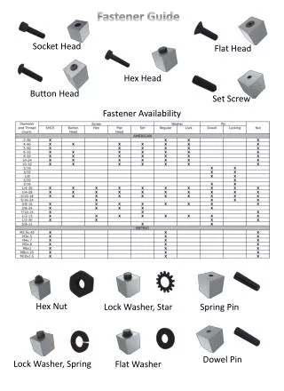
Z X Fcs Gcs Fic’ Gic’ Fsc Gsc Fic Gic Subscripts b – rail base p – pad i – insulator clip bearing area c – clip s – shoulder o – insulator post t - tie Fbi Gbi Fbo’ Fos Gbi’ Legend • Reaction • Friction • Input Load F = Field G = Gauge B = Base Fbi’ Fbo Bbp Bbp’ Fps Bpr Fcs’ Bpr’ Gcs’ Fsc’ Fos’ Gsc’ Fps’ Fts Gst Fst
Distribution of Vertical Wheel Loads 95% 20 kips Source: Amtrak, Edgewood, MD, October 2011
Areas of Investigation Rail • Stresses at rail seat • Strains in the web • Displacements of head/base Fasteners/ Insulator • Strain of fasteners • Stresses on insulator Concrete Crossties • Internal strains • Midspan • Rail Seat • Stresses at rail seat • Global displacement of the crosstie
Planned Locations for Field Testing • Monticello Railway Museum • Transportation Technology Center (TTC) • July 2012 • November 2012 • Spring 2013 • Class I Railroads • Amtrak • BNSF • Union Pacific Transportation Technology Center (TTC)
Future Work • Evaluation and analysis of WILD data to better evaluate input loads • Major discussion point from AREMA Committee 30, Subcommittee 4 (Concrete Tie Technology) Meeting • Conduct laboratory and field testing to gain further insight on loads transferred through each component • Development of greater understanding of dynamic interactions between system components • Utilize output from instrumentation and modeling efforts to establish loading environment
Path Forward • Development of System Level Tie and Fastener Model • Field and Laboratory Testing of Components and Systems • Materials Research and Improvements (all components) • Understand how deterioration methods are related to differing axle loadings (important on shared corridors) • Development of mechanistic design procedures Adoption into AREMA Recommended Practices • Ultimateobjective increase safety and lower life cycle costs of the crosstie and fastening system
Acknowledgements FRA Tie and Fastener BAAIndustryPartners: • Funding for this research has been provided by theFederal Railroad Administration (FRA) • Industry Partnership and support has been provided by • Union Pacific (UP) Railroad • BNSF Railway • National Railway Passenger Corporation (Amtrak) • Amsted RPS / Amsted Rail, Inc. • GIC Ingenieríay Construcción • Hanson Professional Services, Inc. • CXT Concrete Ties, Inc., LB Foster Company
Contact Information Brandon Van Dyk Graduate Research Assistant e-mail: vandyk2@illinois.edu Marcus Dersch Research Engineer e-mail: vandyk2@illinois.edu Riley Edwards Lecturer e-mail: jedward2@illinois.edu