Design Entry: Schematic Capture and VHDL
300 likes | 585 Views
Design Entry: Schematic Capture and VHDL. ENG241 Week #4. References. Kenneth Sort, “VHDL For Engineers”, Prentice Hall, 2009. Peter Ashenden, “The designer’s guide to VHDL, 2 nd edition”, Morgan Kaufmann publishers, 2002. Douglas Perry, “VHDL”, 3 rd Edition, McGraw Hill.

Design Entry: Schematic Capture and VHDL
E N D
Presentation Transcript
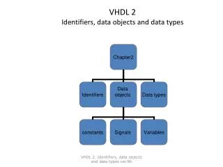
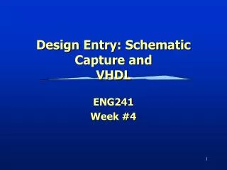
Design Entry: Schematic Capture andVHDL ENG241 Week #4
References • Kenneth Sort, “VHDL For Engineers”, Prentice Hall, 2009. • Peter Ashenden, “The designer’s guide to VHDL, 2nd edition”, Morgan Kaufmann publishers, 2002. • Douglas Perry, “VHDL”, 3rd Edition, McGraw Hill. • Sudhakar Yalamanchili, “Introductory VHDL: From Simulation to Synthesis”, Prentice Hall, 2001. • Sudhakar Yalamnachili, “VHDL: A Starter’s Guide”, 2nd Edition, Prentice Hall, 2005.
Digital System Design IDEA Behavioral Design Behavioral Simulation Structural Design Structural Simulation Logic Design Gate level Simulation Physical Design Device level Simulation Implement Testing ASIC FPGA
Terminology • Functional/Behavioral modeling • Describes the functionality of a component/system • For the purpose of simulation and synthesis • Structural modeling • A component is described by the interconnection of lower level components/primitives • For the purpose of synthesis and simulation • Synthesis: • Translating the HDL code into a circuit, which is then optimized
Computer-Aided Design (CAD) • Circuits of today’s complexity rely on design tools • In this course we will be using Xilinx ISE Foundation to enter our designs • We will also use an FPGA (Field Programmable Gate Array) to map our design onto the FPGA.
Design Entry • Schematic capture • What you will do in the lab. • Hardware Description Language (HDL) • VHDL • Verilog • Electronic System Level (ESL) Higher level possible – C-like and Java-like • ImpulseC, HandelC, Catapult C
What is HDL? • Hardware Description Languages (HDLs) are languages used to • document (model), • Communicate design, • simulate, and • synthesize digital circuits and systems.
VHDL: Introduction • VHDL is an acronym for “VHSIC Hardware Description • Language”. • VHSIC is an acronym for “Very High Speed Integrated • Circuits” program. It was a US government • sponsored program that was responsible for • developing a standard HDL. • VHDL supports modeling and simulation of digital • systems at various levels of design abstraction.
Internal Functionality External Interface Basic Modeling Concepts circuit A E B Outputs Inputs
Entity name Port name Port Port mode Basic Modeling Concepts External Interface modeled by “entity” VHDL construct. • entity ckt1 is • port (X,Y,Z : in bit; • F : out bit); • end entity ckt1; VHDL “port” construct models data input/output.
Entity name Architecture name Basic Modeling Concepts Internal Functionality modeled by “architecture” VHDL construct • architecture behav of ckt1 is • begin • F <= X or not Y and Z; • end architecture behav;
Lexical Elements • Comments: • - A comment line in VHDL is represented by two • successive dashes “- -”. • A comment extends from “- -” to the end of • the line. • Identifiers: • Identifiers are names that can be given by the • user. • rules: • >> must start with an alphabetic letter. • >> can contain alphabetic letters, decimal • digits and underline character “_”. • >> cannot end with “_”. • >> cannot contain successive “_”.
Legal vs. Illegal Identifiers • Valid identifiers • A, X0, counter, Next_Value • Invalid identifiers • last@value contains illegal character • 5bit_coutner starts with nonalphabetic • _A0 starts with an underline • A0_ ends with underline • clock__pulses two successive underlines
Libraries • A library refers to a collection of declarations • (type, entity, sub-program) and their • implementations (architecture, sub-program body). • The actual specification of a library varies from • one simulation package to another. • In VHDL we usually use the IEEE library and have • to declare that at the beginning of our VHDL • program.
Library: Example • For standard logic (std_logic) the basic package is • ieee.std_logic_1164. • This package defines the values and basic logic • operators for type std_logic. • The declarations can be made visible in our model • file by : library IEEE; Use IEEE.STD_LOGIC_1164.ALL; Library Package
Complete Program • -- Library Declaration • Library IEEE; • Use IEEE.std_logic_1164; • -- Entity Declaration • Entity ckt1 is • Port (X,Y,Z : in std_logic; • F : out std_logic); • end ckt1; • -- Architecture Declaration • architecture behav of ckt1 is • begin • F <= X or not Y and Z; • end architecture behav;
Bit type • Bit is also a predefined enumerated type type bit is (‘0’, ‘1’); • Operations • Logical:=, /=, <, >, <=, >= • Boolean:and, or, nand, nor, xor, xnor, not • Shift:sll, srl, sla, sra, rol, ror
Synthesizable VHDL VHDL for Specification VHDL for Simulation VHDL for Synthesis VHDL for Synthesis VHDL for Synthesis of Arithmetic Circuits
Xilinx FPGA, abstract view An FPGA is an integrated circuit that stands for Field Programmable Gate Array (programmed in the Field!). It is capable of mapping any type of digital circuit without the need to wire components.
Generic FPGA architecture: Configurable Logic Block (CLB) Connection Block Wire segments Switch Block Routing Channels I/O pad ENG6530 RCS
LUT implementation LUT A B Z A C D B Z C D Gate implementation Programmable Boolean Functions • Memory units can be used to implement a Boolean function by storing the output of the truth table in the memory and accessing the values by using variables of the truth table as address lines. ENG6530 RCS
ABC f1 f2 f1 D E F f3 f2 f3 Programming an FPGA? A B C D E F Mapping Placement Routing
Mapping the Design onto Digilent FPGA Board Netlist • -- Library Declaration • Library IEEE; • Use IEEE.std_logic_1164; • -- Entity Declaration • Entity ckt1 is • Port (X,Y,Z : in std_logic; • F : out std_logic); • end ckt1; • -- Architecture Declaration • architecture behav of ckt1 is • begin • F <= X or not Y and Z; • end architecture behav; Synthesis Map, Place and Route Generate Bitstream Download 000111010100000000011111001010101010000010100101010101010001100101010110011000
fMRI and Real-time Human Body Imaging • Technique for determining which parts of the brain are activated by different types of physical sensation or activity – “brain mapping” • High- and low-resolution scans compared using numerous FFTs • Image registration (mapping Xray/CT Scan/MRI) requires high performance computing • Much error correction needed due to subject movement • 3D data representation requires a good deal of conventional processing • Studying how RC devices can achieve real-time processing
Biomechanical Kinematics • Knee-joint simulation* • Build a generic model to predict human movement (jumping, walking, etc) • Used to study joint replacement stresses without risking patient injury • Biomechanical simulations frequently use costly optimization methods • Studying how RC-based parallel processing can increase performance
Satellite Imaging • Satellite imaging used for mapping, environmental studies and defense applications • High-data rate and low-power demands of space require cutting-edge technology such as RC to provide required processing capabilities • Including RC devices in the processing chain will eventually enhance performance c/o US Air Force c/o LANL c/o LANL GMTI processing chain