Download
1 / 86
1k likes | 1.57k Views
Review CR & DIGITAL IMAGING (1) 2012 – RT 244 wk 15. References: Bushong Vol 9 www.sprawls.org/resources/DIGRAD/classroom.htm. Objectives. Digital imaging review Review CR fundamentals. Digital Imaging.

E N D
Review CR & DIGITAL IMAGING (1)2012 – RT 244 wk 15 References: Bushong Vol 9 www.sprawls.org/resources/DIGRAD/classroom.htm
Objectives • Digital imaging review • Review CR fundamentals
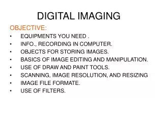
Digital Imaging • Image acquisition that produces an electronic image that can be viewed and manipulated on a computer. • Examples?
Methods to Digitize an Image • 1. Film Digitizer • 2. Video Camera (vidicon or plumbicon) • 3. Computed Radiography • 4. Direct Radiography • PACS • DICOM
Digital Radiography DDR CR Direct Capture Indirect Capture Computed Radiography (CR) - PSL Direct-to-Digital Radiography (DDR)-Selenium Direct-to-Digital Radiography Silicon Scint. Laser Scanning Digitizers
Computer Language • Computers operate on the Binary Number System • It has only two digits, 0 and 1 • Computers function by converting all data into binary values.
Byte • Represents one character, digit, or value. • A bit describes the smallest unit of measure 0 or 1 – computers ultimately understand only 0 or 1 • Byte are 8 bits • A kilobyte represents 1024 bytes, megabyte is 1 million bytes, gigabyte is approximately 1 billion bytes
Basics of Digital Images • digital images are a (matrix) of pixel (picture element) values
Computed Radiography Fundamentals of Computerized Radiography
CR SYSTEM COMPONENTS What are the CR system components?
CR SYSTEM COMPONENTS • CASSETTES (phosphor plates) • ID STATION • IMAGE PREVIEW (QC) STATION • DIGITIZER • VIEWING STATION
Imaging Plate (IP) • Contained in a cassette • Handled the same as S/F cassettes • Processed more like daylight processor with no chemicals • IP has lead backing to reduce scatter
CR – PSP plate • photostimulable phosphor (PSP) plate • Exit photons energizes the PSP plate • The energy is stored in traps on plate (latent image) • PLATE scanned in CR READER
Imaging Plate Construction • A thin sheet of plastic • IP’s have several layers • A protective layer. This is a very thin, tough, clear plastic that protects the phosphor layer • A phosphor or active layer. This is a layer of photostimulable phosphor that “traps” electrons during exposure
Active Layer - Crystals • The materials that make up the PSP plate are from the barium fluorohalide family. • Barium fluorohalide, chlorohalide, or bromohalide crystals. The most common crystal uses is barium fluorohalide with europium
Acquiring the Image What is the correct order? • Violet light is captured by PMT – is amplified and converted into a digital signal • cassette is put into the reader, the imaging plate is extracted • light is sent to the analog to digital converter (ADC). To convert light to binary. • e- return to ground state, visible light is emitted • remnant beam interacts with electrons in the barium fluorohalide crystals • imaging plate is scanned with a helium laser beam or solid-state laserdiodes
Acquiring the Image • The remnant beam interacts with electrons in the barium fluorohalide crystals. This interaction stimulates, or gives energy to, electrons in the crystals, allowing them to enter the conductive layer, where they are trapped in an area of the crystal known as the color or phosphor center. • This trapped signal will remain for hours, even days, although deterioration begins almost immediately. IR should be processed as soon as possible. • The trapped signal is never completely lost.
Imaging Plate Construction • A reflective layer. This is a layer that sends light in a forward direction when released in the cassette reader. This layer may be black to reduce the spread of stimulating light and the escape of emitted light. Some detail is lost in this process.
Needle PSP increase the absorption of x-rays and limit the spread of light emission
IP Design • Designed to optimize the intensity of light release. (CE) • Enhance the absorption of x-rays (DQE) • Limit the spread of light emission for more detail.
Photostimulable Luminescence • When the cassette is put into the reader, the imaging plate is extracted and scanned with a helium laser beam or, in more recent systems, solid-state laserdiodes. This beam, about 100μm wide with a wavelength of 633 nm (or 670 to 690 nm for solid state), scans the plate with red light in a raster pattern and gives energy to the trapped electrons.
X-ray interaction with a PSP screen 1 X-ray interactions with the screen phosphors causes an e- to excited 2 When e- return to ground state visible light is emitted
CR Phosphor Plates ABSORPTION EMISSION LASER STIMULATION ELECTRON TRAP ELECTRON TRAP X-RAY LIGHT
CR Reader – PSP plate • Stimulates the matrix of trapped E- by a RED OR ULTRAVIOLET laser light • Trapped E- energy is released in a form of VIOLET/BLUE light • Violet light is captured by PMT – is amplified and converted into a digital signal
Producing a PSL signal • 50% of the excited e- return to ground state immediately, resulting in light (VIOLET/BLUE) emission. • Slow scan = plate • Fast scan = laser
How CR works • Released light is captured by a PMT (photo multiplier tube). An ultrasensitive photomultiplier tube or CCD (charged couple device) • PSP light is amplified by the PMT or CCD • This light is sent to the analog to digital converter (ADC). To convert light to binary.
Three possibilities include processing methods to: Adjust and optimize the image contrast characteristics LUT & Processing Algorithms Reduce image noise Increase visibility of detail Some type of digital image processing is used with most of the medical imaging modalities. Processing of digital images can be used to change most image characteristics.
Brightness & Contrast • Optimum kVp & mAs has changed for digital • kVp changes for SUBJECT contrast – not image contrast • mAs does not influence DENSITY the same as it did with F/S • The image is POSTPROCESSED – with changing PROCESSING ALGORITHMS
digital processing methods that can be used to adjust the contrast characteristics of an image. • Look Up Table (LUT) processing • Windowing • Are used in digital radiography as well as with many of the other imaging modalities.
Dynamic Range • The range of exposure values to which the • image receptor will respond. • The greater the range of values that a • receptor will respond to the greater the • dynamic range.
Characteristic curve of radiographic film
Widow level & width Same photons at the image receptor Image is post processed – changing Brightness and contrast of image appearance
The ability to window is a valuable feature of all digital images. Windowing is the process of selecting some segment of the total pixel value range and then displaying the pixel values within that segment over the full brightness (shades of gray) range from white to black.
windowing • Important point...Contrast will be visible only for the pixel values that are within the selected window. • All pixel values that are either below or above the window will be all white or all black and display no contrast. • The person controlling the display can adjust both the center and the width of the window. The combination of these two parameters determine the range of pixel values that will be displayed with contrast in the image.