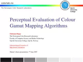
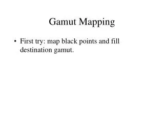
Gamut Mapping
Gamut Mapping. First try: map black points and fill destination gamut. device gamut. image gamut. device gamut. translate B i to B d. image gamut. device gamut. translate B i to B d. image gamut. scale by csf. device gamut. translate B i to B d. image gamut. scale by csf.

Gamut Mapping
E N D
Presentation Transcript
Gamut Mapping • First try: map black points and fill destination gamut.
device gamut image gamut
device gamut translate Bito Bd image gamut
device gamut translate Bito Bd image gamut scale by csf
device gamut translate Bito Bd image gamut scale by csf rotate
Gamut Mapping Xd = Bd + csf R (Xi - Bi) Bi = image black, Bd = destination black R = rotation matrix csf = contrast scaling factor Xi = image color, Xd = destination color Problems: Image colors near black outside of destination are especially bad: loss of detail, hue shifts due to quantization error, ...
Xd = Bd + csf R (Xi - Bi) + bs (Wd- Bd) shift and scale alongdestination gray
Fig 14a, bs>0, csf small, image gamut maps entirelyinto printer gamut, but contrast is low. Fig 14b, bs=0, csf large, more contrast, more colors inside printer gamut, butalso more outside.
Saturation control • “Umbrella transformation” [Rs Gs Bs] = monitor whitepoint [Rn Gn Bn] new RGB coordinates such that Rs + Gs + Bs =Rn + Gn + Bnand [Rn Gn Bn] maps inside destination gamut First map R Rs+G Gs+B Bsto R Rn+G Gn+B Bn Then map into printer coordinates Makes minor hue changes, but “relative” colors preserved. Achromatic remain achromatic.
Projective Clipping • After all, some colors remain outside printer gamut • Project these onto the gamut surface: • Try a perpendicular projection to nearest triangular face in printer gamut surface. • If none, find a perpendicular projection to the nearest edge on the surface • If none, use closest vertex
Projective Clipping • This is the closest point on the surface to the given color • Result is continuous projection if gamut is convex, but not else. • Bad: want nearby image colors to be nearby in destination gamut.
Projective Clipping • Problems • Printer gamuts have worst concavities near black point, giving quantization errors. • Nearest point projection uses Euclidean distance in XYZ space, but that is not perceptually uniform. • Try CIELAB? SCIELAB? • Keep out of gamut distances small at cost of use of less than full printer gamut use.