Download

1 / 8
90 likes | 165 Views
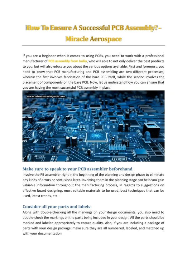
Printed Circuit Boards (PCBs) used in aerospace and military applications demand high reliability due to their harsh operating conditions. Unlike the regular PCB, these circuit boards are exposed to extreme environmental conditions, chemicals, contaminants, etc.

E N D
Printed Circuit Boards (PCBs) used in aerospace and military applications demand high reliability due to their harsh operating conditions. Unlike the regular PCB, these circuit boards are exposed to extreme environmental conditions, chemicals, contaminants, etc. This is why these PCBs are mandated to meet IPC-A-610E Class 3 standards, which is set for high-performance electronic products. The class 3 standards requires electronic products to provide continual performance in uncommonly harsh environments without any downtime. Hence, military and aerospace PCBs require special considerations in terms of fabrication, design, and assembly. This post discusses those considerations and applications of these PCBs in military and aerospace equipment.
Design Considerations for Military and Aerospace PCB Assembly Any PCB assembly proceeds in a pre-set pattern. It is no different for aerospace and military PCB assembly too. However, the following are some special design considerations to be made to meet IPC standards. All components used should be of Mil-spec grade. These components have tight tolerances ranging from 1-2%. The commercial grades have tolerances of 5-10%, which is not recommended. PCBs should be designed to handle the maximum current load. Low-frequency components should be clearly differentiated from high-frequency ones. Some high frequency components produce waveforms, which may affect the low frequency components. The waveforms introduce noise and degrade the quality of the signal, which is unacceptable for military and aerospace products. Clock signals should be shielded and clean. This can be achieved by creating physical shielding in the design stage. Physical shielding is created using material enclosures made from aluminium or similar material. Quality heat resistant materials should be used because it helps withstand high temperatures. Some of these materials may include Pyralux AP, FR408, and other metallic core components. Thermal compounds should be used wherever heat dissipation becomes a necessity. Pre-layout simulations and impedance should be made to understand how the PCB will work in real environments.
High heat producing components require large clearance space than regular components. Hence, care should be taken to increase their clearance space while mounting. This helps avoid heating of nearby components and protects the PCB. Braided and stranded wires should be pre-tinned for better solderability. Press-fit components should be soldered to avoid vibration. Thermal profiles for wave and reflow soldering processes should be rechecked before the assembly. This helps avoid component damage during the assembly process. The finishing material should be chosen such that it supports the PCB to perform in harsh environmental conditions. Some of the most popular finishing materials used for the purpose are: Electrolytic nickel and gold Electroless Nickel with Immersion Gold Coating (ENIG) Lead-free HASL Immersion Silver Electrolytic wire bondable gold HASL
Acrylic based sprays should be used for conformal coating of the PCBs. This helps protect the final PCB. High quality software simulation programs should be used to check the PCB design. This helps in verifying loads at different locations and understand design alterations to be made. PCB routings should be maintained at 45-degree angles or at lesser angles. This helps smooth current transmission through the circuit. Military and aerospace PCBs should be manufactured in conformance to MIL-PRF-50884, MIL-PRF-31032, and MIL-PRF-55110 standards.
Aerospace Industry Applications Using PCBs Following are some of the aerospace applications using IPC-A-610E Class 3 PCBs Satellite equipment Digitalized signal and microwave processing systems Central Air Data Computers (CADC) Ground station applications Passive detection systems Full Authority Digital Engine Control Systems (FADEC) Electronic flight instrumentation systems
Military Industry Applications Using PCBs Following are some of the military applications using special PCBs Unmanned vehicles Defense navigation and communication systems Robotic systems Satellite subsystems using embedded processors Ruggedized computers Artillery and mortars Base/camp protection and security
Above-mentioned design considerations and applications will help you understand why military and aerospace PCB assembly requires a meticulous approach. You can understand that failure of these PCBs not only affect the application, but also the purpose. For more information about Military and Aerospace PCB Assembly, please visit http://www.acceleratedassemblies.com. Accelerated Assemblies Inc., 725 Nicholas Blvd. Suite A Elk Grove Village, IL 60007 CALL NOW! (630) 616-6680 http://www.acceleratedassemblies.com/ info@acceleratedassemblies.com