Download
1 / 36
360 likes | 496 Views
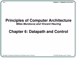
Principles of Computer Architecture Miles Murdocca and Vincent Heuring Chapter 6: Datapath and Control. Chapter Contents. 6.1 Basics of the Microarchitecture 6.2 A Microarchitecture for the ARC 6.3 Hardwired Control 6.4 Case Study: The VHDL Hardware Description Language.

E N D
Principles of Computer ArchitectureMiles Murdocca and Vincent HeuringChapter 6: Datapath and Control
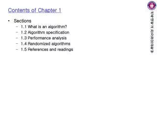
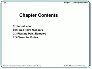
Chapter Contents • 6.1 Basics of the Microarchitecture • 6.2 A Microarchitecture for the ARC • 6.3 Hardwired Control • 6.4 Case Study: The VHDL Hardware Description Language
The Fetch-Execute Cycle • • The steps that the control unit carries out in executing a program are: • (1) Fetch the next instruction to be executed from memory. • (2) Decode the opcode. • (3) Read operand(s) from main memory, if any. • (4) Execute the instruction and store results. • (5) Go to step 1.
High Level View of Microarchitecture • • The microarchitecture consists of the control unit and the programmer-visible registers, functional units such as the ALU, and any additional registers that may be required by the control unit.
Branch Decoding • • Decoding tree for branch instructions shows corresponding microprogram lines:
Example: Add the subcc Instruction • • Consider adding instruction subcc (subtract) to the ARC instruction set. subcc uses the Arithmetic format and op3 = 001100.
Branch Table • • A branch table for trap handlers and interrupt service routines:
Microprogramming vs. Nanoprogramming • • (a) Micropro-gramming vs. (b) nano-programming.
Hardware Description Language • • HDL sequence for a resettable modulo 4 counter.
Circuit Derived from HDL • • Logic design for a modulo 4 counter described in HDL.
HDL for ARC • • HDL description of the ARC control unit.
HDL ARC Circuit • • The hardwired control section of the ARC: generation of the control signals.
HDL ARC Circuit (cont’) • • Hardwired control section of the ARC: signals from the data section of the control unit to the datapath.
Case Study: The VHDL Hardware Description Language • • The majority function. a) truth table, b) AND-OR implementation, c) black box representation.
VHDL Specification • Interface specification for the majority component • -- Interface • entity MAJORITY is • port • (A_IN, B_IN, C_IN: in BIT • F_OUT: out BIT); • end MAJORITY; • Behavioral model for the majority component • -- Body • architecture LOGIC_SPEC of MAJORITY is • begin • -- compute the output using a Boolean expression • F_OUT <= (not A_IN and B_IN and C_IN) or • (A_IN and not B_IN and C_IN) or • (A_IN and B_IN and not C_IN) or • (A_IN and B_IN and C_IN) after 4 ns; • end LOGIC_SPEC;
VHDL Specification (cont’) • -- Package declaration, in library WORK • package LOGIC_GATES is • component AND3 • port (A, B, C : in BIT; X : out BIT); • end component; • component OR4 • port (A, B, C, D : in BIT; X : out BIT); • end component; • component NOT1 • port (A : in BIT; X : out BIT); • end component; • -- Interface • entity MAJORITY is • port • (A_IN, B_IN, C_IN: in BIT • F_OUT: out BIT); • end MAJORITY;
VHDL Specification (cont’) • -- Body • -- Uses components declared in package LOGIC_GATES • -- in the WORK library • -- import all the components in WORK.LOGIC_GATES • use WORK.LOGIC_GATES.all • architecture LOGIC_SPEC of MAJORITY is • -- declare signals used internally in MAJORITY • signal A_BAR, B_BAR, C_BAR, I1, I2, I3, I4: BIT; • begin • -- connect the logic gates • NOT_1 : NOT1 port map (A_IN, A_BAR); • NOT_2 : NOT1 port map (B_IN, B_BAR); • NOT_3 : NOT1 port map (C_IN, C_BAR); • AND_1 : AND3 port map (A_BAR, B_IN, C_IN, I1); • AND_2 : AND3 port map (A_IN, B_BAR, C_IN, I2); • AND_3 : AND3 port map (A_IN, B_IN, C_BAR, I3); • AND_4 : AND3 port map (A_IN, B_IN, C_IN, I4); • OR_1 : OR3 port map (I1, I2, I3, I4, F_OUT); • end LOGIC_SPEC;