Download
1 / 22
220 likes | 236 Views
This article discusses the advancements in squeeze injection technology for Enhanced LIGO gravitational wave detectors, aiming to increase sensitivity and reduce quantum noise. It explores the use of squeezed vacuum states and the integration of components for improved performance. The control system, interferometer setup, and noise models are detailed, highlighting the efforts to enhance detector capabilities.

E N D
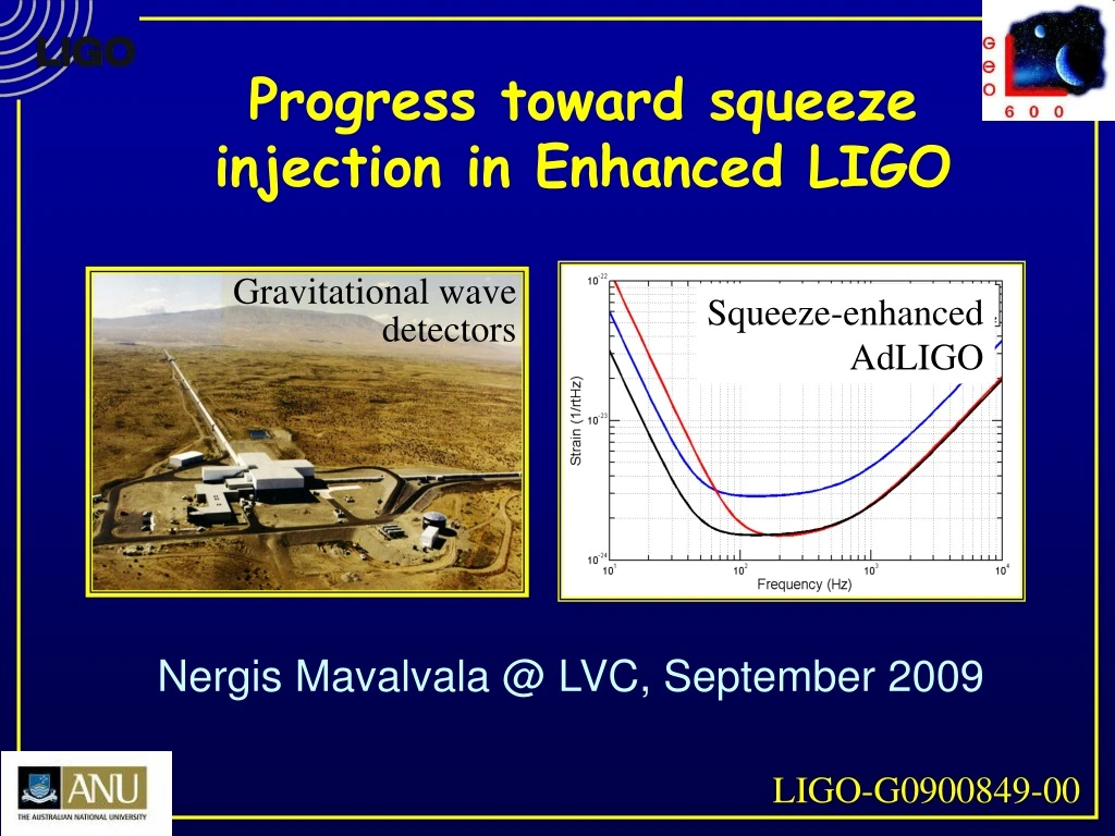
Gravitational wavedetectors Progress toward squeeze injection in Enhanced LIGO Squeeze-enhancedAdLIGO Nergis Mavalvala @ LVC, September 2009 LIGO-G0900849-00
Advanced LIGO with squeeze injection Radiation pressure Shot noise Power higher by 4x OR 6 dB squeeze injection
X2 X1 X2 Shot noise limited (number of photons)1/2 Arbitrarily below shot noise X1 X2 X2 Vacuum fluctuations Squeezed vacuum X1 X1 Quantum Noise in an Interferometer Radiation pressure noise Quantum fluctuations exert fluctuating force mirror displacement Laser
How to squeeze? • My favorite way • A tight hug
Squeezing injection Second harmonic generator (SHG) • Convert 1064 nm 532 nm with ~50% efficiency Optical parametric oscillator (OPO) • Few 100 mW pump field (532 nm) correlatesupper and lower quantum sidebands around carrier (1064 nm) squeezing Balanced homodyne detector • Beat local oscillator at 1064nm with squeezed field Laser IFO OPO Faraday rotator ASPD SHG
Goals of H1 test • Inject 6 dB of squeezing into the antisymmetric (AS) port of H1 • Measure 3 dB of improved SNR at frequencies where interferometer is shot noise limited • Ensure that no deleterious effects at all other frequencies in detection band • Low noise performance test is remaining critical step to implementation in Advanced LIGO
The H1 squeezer components • Initial LIGO 10 W MOPA pumps… • AEI-designed SHG 300 to 500 mW of 532 nm (green) • ANU-designed and built traveling wave OPO • LIGO-designed and built electronics • Integration and testing at MIT and LHO
Control System Interferometer S0 HomodyneDetector Fiber (PSL) Faraday S4 Laser 0 SHG OPO S3 S1 S5 S2 OMC Auxiliary Laser 1 AS Port Squeezer DC 10
Servo Model • S0Frequency lock Laser 0 to PSL using FSS • S1 Frequency lock Laser 1 (auxiliary ) to Laser 0 using FSS • S2 Phase lock Laser 1 to green light using feedback to PZT & Laser 1 additive offset • S3 Phase lock squeeze angle to AS port light using feedback to PZT & Laser 0 additive offset (LO lock) • S4 Lock SHG to Laser 0 with PDH to cavity PZT • S5 Lock OPO to green with PDH to cavity PZT
Simulink Model Sigg, Dwyer et al. LIGO-T0900325-v1
Servo Model Fiber Stabilization not needed Laser 0 is frequency locked to main interferometer laser (PSL) and phase locked to AS port light
Noise Model Highlights • Acoustic couplings • Direct back scattering under control • Requirement • OMC has • Require second in-vacuum Faraday • OPO ring topology is very helpful Motion of scatterer Backscatter reflectivity
Noise Model Highlights • Phase noise requirement < 50 mrad rms • Squeeze angle deviation • Remaining RF sidebands transmitted through OMC are important Detected quadrature Anti-squeezeprojection Phase Noise (°) Squeeze angledeviation PCR/PCD
Noise Model Highlights • Other noise couplings • Laser frequency noise not important due to large servo bandwidth (500 kHz) • Path length variations not important due to large servo bandwidth (few kHz) • Shot noise: 1 mW per detector should be enough • OPO length fluctuations are not suppressed by Local Oscillator (LO) servo
ANU Traveling Wave OPO PZT Actuator Squeezing Out Pump light In Oven/ Temperature Sensor Crystal 150 mm 200 mm 18
ANU OPO Squeezing Performance Electronics Mains harmonics Cross coupling from Coherent Lock Quantum noise • Electronic Noise? Lab environment Acoustic Noise 6dB Observed squeezing 8dB Inferred squeezing H1 Squeezer Status 19
Schedule and Planning • Reviewed, approved and funded (08/2009) • ANU will continue on development of OPO • On track for Spring 2010 delivery • MIT will continue with SHG & laser locking • On track to begin integration with OPO in Spring 2010 • Electronics production at LHO moving forward • RF, PDs, TTFFS and length servos (common mode board) to arrive at MIT December 2009 • Planning for installation in Feb. 2011 • Depends on Advanced LIGO commissioning sequence and S6
Highlights and summary • Outstanding team assembled • Graduate students Sheila Dwyer (MIT), Sheon Chua (ANU) and Michael Stefsky (ANU), Alexander Khalaidovski (AEI) • Led by Daniel Sigg at LHO • Impressive progress on OPO development at ANU • 6 dB of squeezing observed • Traveling wave bowtie design works • Laser, optical table and clean room installed at MIT • AEI loaner SHG at MIT producing green • Entering optimization phase • In the process of building our own (copy of AEI design) • Noise model and simulation done • Electronics design done for RF distribution • Shared with advanced LIGO
GWDetector Laser The End Faraday isolator SHG OPO HomodyneDetector Squeeze Source GW Signal