Download
1 / 51
510 likes | 645 Views
Chapter 6 Topologies and Access Methods. Network+ Guide to Networks, Fourth Edition. Objectives. Describe the basic and hybrid LAN physical topologies, and their uses, advantages and disadvantages Describe the backbone structures that form the foundation for most LANs

E N D
Chapter 6 Topologies and Access Methods Network+ Guide to Networks, Fourth Edition
Objectives • Describe the basic and hybrid LAN physical topologies, and their uses, advantages and disadvantages • Describe the backbone structures that form the foundation for most LANs • Compare the different types of switching used in data transmission
Objectives (continued) • Understand the transmission methods underlying Ethernet, Token Ring, FDDI, and ATM networks • Describe the characteristics of different wireless network technologies, including Bluetooth and the three IEEE 802.11 standards
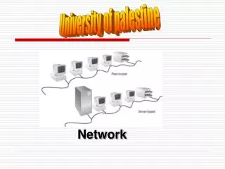
Simple Physical Topologies • Physical topology:physical layout of nodes on a network • Three fundamental shapes: • Bus • Ring • Star • May create hybrid topologies • Topology integral to type of network, cabling infrastructure, and transmission media used
Bus • Single cable connects all network nodes without intervening connectivity devices • Devices share responsibility for getting data from one point to another • Terminators stop signals after reaching end of wire • Prevent signal bounce • Inexpensive, not very scalable • Difficult to troubleshoot, not fault-tolerant
Bus (continued) Figure 6-1: A terminated bus topology network
Ring Figure 6-2: A typical ring topology network
Star Figure 6-3: A typical star topology network
Star (continued) • Any single cable connects only two devices • Cabling problems affect two nodes at most • Requires more cabling than ring or bus networks • More fault-tolerant • Easily moved, isolated, or interconnected with other networks • Scalable • Supports max of 1024 addressable nodes on logical network
Hybrid Physical Topologies: Star-Wired Ring Figure 6-4: A star-wired ring topology network
Star-Wired Bus Figure 6-5: A star-wired bus topology network
Backbone Networks: Serial Backbone • Daisy chain: linked series of devices • Hubs and switches often connected in daisy chain to extend a network • Hubs, gateways, routers, switches, and bridges can form part of backbone • Extent to which hubs can be connected is limited
Backbone Networks: Serial Backbone (continued) Figure 6-6: A serial backbone
Distributed Backbone Figure 6-8: A distributed backbone connecting multiple LANs
Collapsed Backbone Figure 6-9: A collapsed backbone
Parallel Backbone Figure 6-10: A parallel backbone
Logical Topologies • Logical topology: how data is transmitted between nodes • May not match physical topology • Bus logical topology: signals travel from one network device to all other devices on network • Required by bus, star, star-wired physical topologies • Ring logical topology: signals follow circular path between sender and receiver • Required by ring, star-wired ring topologies
Switching: Circuit Switching • Switching: component of network’s logical topology that determines how connections are created between nodes • Circuit switching: connection established between two network nodes before transmission • Bandwidth dedicated to connection • Remains available until communication terminated • While connected, all data follows same path initially selected by switch • Can result in waste of available resources
Message Switching • Establishes connection between two devices, transfers information, then breaks connection • Information then stored and forwarded from second device to third device on path • “Store and forward” routine continues until message reaches destination • All information follows same physical path • Requires that each device in data’s path have sufficient memory and processing power to accept and store information
Packet Switching • Breaks data into packets before transmission • Packets can travel any network path • Contain destination address and sequencing information • Can attempt to find fastest circuit available • When packets reach destination node, they are reassembled • Based on control information • Not optimal for live audio or video transmission • Efficient use of bandwidth
Ethernet: CSMA/CD (Carrier Sense Multiple Access with Collision Detection) • Access method: method of controlling how network nodes access communications channels • CSMA/CD: Ethernet’s access method • Ethernet NICs listen on network • Wait until no nodes transmitting data over the signal on the communications channel before transmission • Several Ethernet nodes can be connected to a network and can monitor traffic simultaneously
Ethernet: CSMA/CD (continued) • Collision: two transmissions interfere with each other • Common on heavy-traffic networks • Can corrupt data or truncate data frames • Jamming: NIC indicates to network nodes that previous transmission was faulty • Collision domain: network portion in which collisions occur • Data propagation delay: length of time data takes to travel between segment points
Ethernet: CSMA/CD (continued) Figure 6-11: CSMA/CD process
Switched Ethernet • Shared Ethernet: fixed amount of bandwidth • Shared by all devices on a segment • All nodes on segment belong to same collision domain • Switched Ethernet: enables multiple nodes to simultaneously transmit and receive data over different logical network segments • Increases effective bandwidth of network segment
Switched Ethernet (continued) Figure 6-12: A switched Ethernet network
Ethernet Frames • Ethernet networks may use one (or a combination) of four kinds of data frames: • Ethernet_802.2 (“Raw”) • Ethernet_802.3 (“Novell proprietary”) • Ethernet_II (“DIX”) • Ethernet_SNAP • Frame types differ in way they code and decode packets of data • Ethernet frame types have no relation to network’s topology or cabling characteristics
Using and Configuring Frames • Cannot expect interoperability between frame types • Node’s Data Link layer services must be properly configured for types of frames it might receive • LAN administrators must ensure all devices use same, correct frame type • Most networks use Ethernet_II • Frame types typically specified through device’s NIC configuration software • Most NICs automatically sense frame types running on network and adjust
Frame Fields • Ethernet frame types share many common fields • Every frame contains: • 7-byte preamble and 1-byte start-of-frame delimiter (SFD) • 14-byte header • Destination address • Source address • Additional field that varies in function and size • 4-byte FCS field • Data portion • 46 to 1500 bytes of information
Ethernet_II (“DIX”) Figure 6-13: Ethernet_II (“DIX”) frame
PoE (Power over Ethernet) • IEEE 802.3af standard specifies method for supplying electrical power over Ethernet connections • Useful for nodes far from power receptacles or needing constant, reliable power source • Power sourcing equipment (PSE): device that supplies power • Powered devices (PDs): receive power from PSE • Requires CAT 5 or better copper cabling
Token Ring • Token Ring networks can run at 4, 16, or 100 Mbps • High-Speed Token Ring (HSTR) • Use token-passing routine and star-ring hybrid physical topology • Token passing: 3-byte packet (token) transmitted between nodes in circular fashion around ring • When station has something to send, picks up token, changes it to a frame, adds header, information, and trailer fields • All nodes read frame as it traverses ring
Token Ring (continued) • Token-passing control scheme avoids possibility for collisions • More reliable and efficient than Ethernet • Active monitor: maintains timing for ring passing, monitors token and frame transmission, detects lost tokens, corrects errors • Token Ring connections rely on NIC that taps into network through a MAU • Self-shorting feature of Token Ring MAU ports makes Token Ring highly fault tolerant
Token Ring (continued) Figure 6-14: Interconnected Token Ring MAUs
FDDI (Fiber Distributed Data Interface) • Uses double ring of MMF or SMF to transmit data at speeds of 100 Mbps • First network technology to reach 100 Mbps • Frequently found supporting network backbones installed in late 1980s and early 1990s • Used on MANs and WANs • Links can span distances up to 62 miles • Reliable and secure • Expensive
FDDI (continued) Figure 6-16: A FDDI network
ATM (Asynchronous Transfer Mode) • ITU standard describing Data Link layer protocols for network access and signal multiplexing • Packet called a cell • Always has 48 bytes of data plus 5-byte header • Fixed size provides predictable network performance • Virtual circuits: connections between nodes that logically appear to be direct, dedicated links • Switches determine optimal path • Establish path before transmission • Configurable use of limited bandwidth
ATM (continued) • Typically considered a packet-switching technology • Establishing reliable connection allows ATM to guarantee specific quality of service (QoS) for certain transmissions • Standard specifying data will be delivered within certain period of time • Compatible with other network technologies • LAN Emulation (LANE) allows integration with Ethernet or Token Ring networks
Wireless Networks: 802.11 • Notable standards: 802.11b, 802.11a, 802.11g • Share many characteristics • e.g., Half-duplex signaling • Access Method: • MAC services append 48-bit physical addresses to frames to identify source and destination • Use Carrier Sense Multiple Access with Collision Avoidance (CSMA/CA) to access shared medium • Minimizes potential for collisions • ACK packets used to verify every transmission
Wireless Networks: 802.11 (continued) • Access Method (continued): • Request to Send/Clear to Send (RTS/CTS) protocol enables source node to issue RTS signal to an access point • Request exclusive opportunity to transmit • Association: • Communication between station and access point enabling station to connect to network • Scanning: station surveys surroundings for access point(s)
Wireless Networks: 802.11 (continued) • Association (continued): • Active scanning: station transmits a probe on all available channels within frequency range • Passive scanning: station listens on all channels within frequency range for beacon frame issued from an access point • Contains info required to associate node with access point [e.g., Service Set Identifier (SSID)] • WLANs can have multiple access points • Reassociation: station changes access points
Wireless Networks: 802.11 (continued) Figure 6-17: A WLAN with multiple access points
Wireless Networks: 802.11 (continued) • Frames: • For each function, 802.11 specifies frame type at MAC sublayer • Management frames involved in association and reassociation • Control frames related to medium access and data delivery • Data frames carry data sent between stations
Wireless Networks: 802.11 (continued) Figure 6-18: Basic 802.11 MAC frame format
Bluetooth • Mobile wireless networking standard that uses FHSS RF signaling in 2.4-GHz band • Relatively low throughput and short range • Designed for use on small networks composed of personal area networks (PANs) • Piconets • Piconets consisting of two devices requires no setup • Master and slaves • Multiple Bluetooth piconets can be combined to form a scatternet
Bluetooth (continued) Figure 6-19: A wireless personal area network (WPAN)
Bluetooth (continued) Figure 6-21: A scatternet with two piconets
Infrared (IR) Figure 6-22: Infrared transmission
Infrared (IR) (continued) Table 6-1: Wireless standards
Summary • A physical topology is the basic physical layout of a network; it does not specify devices, connectivity methods, or addresses on the network • A bus topology consists of a single cable connecting all nodes on a network without intervening connectivity devices • In a ring topology, each node is connected to the two nearest nodes so that the entire network forms a circle • In a star topology, every node on the network is connected through a central device, such as a hub
Summary (continued) • LANs often employ a hybrid of more than one simple physical topology • Network backbones may follow serial, distributed, collapsed, or parallel topologies • Switching manages the filtering and forwarding of packets between nodes on a network • Ethernet employs a network access method called CSMA/CD • Networks may use one (or a combination) of four kinds of Ethernet data frames