
Beam Diagnostics for the European Spallation Source (ESS) Linac
This document outlines the beam diagnostics approach for the European Spallation Source (ESS) linac, detailing the use of various monitoring systems to ensure optimal performance and safety. Key parameters include a 5 MW average beam power, 2.5 GeV protons, and specific measurements for beam loss, position, size, and profile with high precision. The integration of ionization chambers, PMTs, and neutron detectors is highlighted, along with ongoing simulations to refine detection strategies. Future specifications will evolve from beam physics studies during the Accelerator Design Update.

Beam Diagnostics for the European Spallation Source (ESS) Linac
E N D
Presentation Transcript
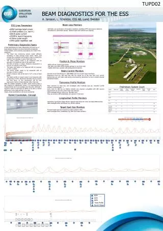
TUPD02 BEAM DIAGNOSTICS FOR THE ESS A. Jansson, L. Tchelidze, ESS AB, Lund, Sweden Beam Loss Monitors ESS Linac Parameters • Will likely use combination of Ionization chambers, scintillator/PMT and neutron detectors. • Simulations to determine optimal detector types and locations are ongoing. • 5MW average beam power • 2.5GeV protons (i.e. not H-) • 50mA pulse current • 352MHz bunch frequency • 2.86ms pulse length • 14Hz pulse repetition rate Preliminary Diagnostics Specs • A final specification for beam diagnostics will come out of beam physics studies to be done during the Accelerator Design Update. Some working assumptions are made in the meantime. • The beam loss monitoring system needs sufficient sensitivity to keep average losses below 1W/m, and enough time resolution and dynamic range to protect the machine from damage in case of fast beam loss. • The beam position needs to be measured with an accuracy of a couple per cent of the beam size. • The time of arrival, or phase, should be measured to a fraction of a degree of RF phase. • The beam size needs to be measured with an accuracy of 10% or better. • The bunch length needs to be measured with an accuracy of 10% or better. • Need to measure halo at the level of 10-5 or less of total beam. • The beam profile on target needs to be measured with an accuracy of 10%. Non-linear elements may be used in the final focus, so this requirement will be best expressed in terms of beam density rather than size. • With the notable exception of BLMs, which need to have a fast response to catastrophic losses, it is assumed that the measurements can be an average over the pulse, although it would be useful (in particular for BPMs) to be able to resolve differences in the head and tail to the train. • Clearly, these specifications will evolve somewhat. Position & Phase Monitors • BPMs will also supply beam phase • Will likely use button BPMs (except perhaps in very front end) • Digital electronics, possibly with analog downconversion. Beam Current Monitors • Several current transformers in LEBT/MEBT, and one at each major transitions. • Experience from e.g. SNS says that with the except ion of the very front end, current transformers are only really used during commissioning (sensitivity too low to detect allowed operational losses). Transverse Profile Monitors • Wire scanners as base line, will investigate other methods (gas jet, ionization profile monitors, luminescense, …) • Early work for SNS by Los Alamos indicate wire scanners compatible with SRF vacuum requirements can be built, carbon best wire material. • Will investigate thinner wires (e.g. Fermilab 1um) • May use screens, SEM grids/harps, slit scanner in front end. Preliminary System Count Hybrid Cryomodule Concept Longitudinal Profile Monitors • Feschenko type Bunch Shape Monitor appears best choice for short (10-40ps) ESS bunches. • Will investigate other techniques (e.g. electro-optical). Target Spot Size Monitors • Foresee target spot size monitoring system similar to SNS. • Will investigate other possibilities (eg. OTR from beam window) BCM BLM BPM Trans Profile Bunch Shape