Download

1 / 21
350 likes | 858 Views
Audio Amplifier Design Tips. May 2012. Why Class A/B?. LM4780 Stereo A/B 60W. Class A/B. Easy design Simple PCB – 1 or 2 layers Fewer components No EMI Better sound quality. Stereo Class D 50W. Class D. Better efficiency Smaller size. Parallel Operation. Features.

E N D
Audio AmplifierDesign Tips May 2012
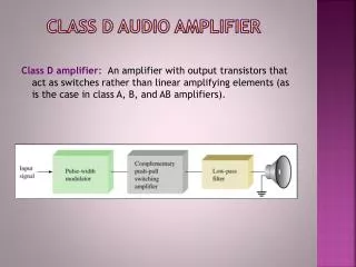
Why Class A/B? LM4780 Stereo A/B 60W Class A/B • Easy design • Simple PCB – 1 or 2 layers • Fewer components • No EMI • Better sound quality Stereo Class D 50W Class D • Better efficiency • Smaller size
Parallel Operation Features • Parallel operation boosts the available output current and is valuable when driving low impedance loads. • Output ballast resistors are needed to make sure the amplifiers are evenly loaded.
Bridge Operation Features • Bridge operation doubles the output voltage swing on the same supple. • The result is up to 4 times the output power • This circuit show how to configure the LM3886 for bridge operation
StabilityWhat to look for Oscillation • Oscillation can develop for many reasons. • The scope photo shows some “fuzz” on the lower side of the sine wave • Oscillation may also occur at all points on the sine wave. Solutions • Snubber • A simple R/C filter on the output will usually fix a bottom side oscillation • Amplifier gain • Most high power audio A/B amplifiers require a voltage gain larger than 10 for stability. • Filter across the feedback resistor may lower the gain and cause oscillation • Power Supply • Bypass caps close to the device. Bypass Caps Snubber Av > 10
Thermal ConsiderationsWhat factors are involved Power Dissipation • All IC’s dissipate power to some degree • Audio power amplifiers generate a significant amount of hear • Power dissipation varies depending on: • Power supply voltage • Output load – 8 or 4 ohms Thermal Resistance • Determined by the path the heat takes to get “out” of the package • qja is referred to as “junction-to-ambient” • qjc is referred to as “junction-to-case” • Heat-sinks also have a thermal resistance specified in Degrees C/W.
Thermal ConsiderationsHow to calculate power dissipation – LM1875 Determine the operating conditions • LM1875 datasheet • Supply voltage = +/- 25V • Load = 8 ohms Calculate PDMax for LM875 • PDMax = (50v)/(2*(3.14)2*8) + (50v*70Ma) • PDMax = 15.85 + 3.5 = 18.85W Use the PDMax equation • PDMax = V2(supply total)/(2*p2RLoad) + PQ
Thermal ConsiderationsPower Dissipation Curves LM1875 The Easy Way • Most datasheet supply a “power dissipation” curve • This is the easy way to determine PDMAX • However, not all condition may be included. • Make sure to pick the correct graph for the load • Find the curve for the Supply Voltage • Locate PDMAX
Thermal ConsiderationsHow hot will the device get? LM1875 Thermal Resistance • The total thermal resistance must be calculated • (LM1875 Qjc + Heat Sink Thermal Resistance) = (3oC/W + 2oC/W) - assume heat-sink of 2oC/W = 5oC/W Max Device Temperature • Assuming a max ambient temperature of 50 deg C, the max device temperature can be calculated • (Thermal resistance)*PDMAX + T(MAX AMBIENT) = (5oC/W) * (18.85W) + 50oC = 144oC • Note: Max temp may not exceed 150oC
Thermal ConsiderationsPower de-rating Curves The Easy Way • Locate PDMAX on the vertical axis • Locate the max ambient temperature on the horizontal axis • Pick the appropriate heasink thermal resistance • Note all lines intersect at a max IC junction temperature of 150oC
PCB LayoutGround Trace Routing Current Flow • Large current flows from the Output Ground to the power supply ground (Blue Arrow) • The trace connecting the two grounds is large, but still has resistance. • This current flow generates a voltage waveform Where is the input ground • In this case the input ground is connected to the output • The signal on the output ground is now transferred to the input ground • This is effectively another signal injected into the input of the amplifier.
PCB LayoutHow to Evaluate Setup • Connect the amplifier load and power supply • Connect the amplifier input and output to a distortion analyzer. • Connect one scope probe to the amplifier output • Connect the “reading” output of the distortion analyzer to another scope input Analysis • The amplifier output signal is shown on the right with the yellow trace. • The “reading” output is shown in green. • The reading trace represents what the analyzer is actually measuring • This particular amplifier has a grounding issue caused by improper connections of the input ground as shown in the last slide
PCB LayoutGround Trace Routing The Fix • The input ground is now disconnected from the output ground. • The ground is routed to the quiet ground (Cap Ground)
PCB Layout Proper Operation • This is the same amplifier as shown in the previous slide • Grounding problem solved • Notice the low distortion levels • Dominant factor is crossover distortion
Audio Power Amplifier Roadmap LME Series 0.0005% THD Overture SPiKe Protection 0.002% THD LME49810 1x400W Driver Relative Performance LM4702 2x125W Driver LM4780 2x60W Overture LM3886 1x70W Overture LM4781,2 3x35W Overture LM3875,76 1x60W Overture Mid Power 0.02% THD LM2876 1x70W Overture LM1875 1x30W LM4752,55 2x11W LM4950 2x3, 1x10W
Output Protection Types of Protection • Thermal Shutdown – turn off the device if it gets too hot • Current limiting – clamp the output current when it gets too large • SOA (Safe Operating Area) Protection – limit the power dissipated in the output transistors Current Flow I V Current Limiting • Current flow through RE to the load • This causes V to rise in value • When V reaches about 0.7 volts, I begins to flow • I pulls the base drive from the output transistors, limiting the output current
Output ProtectionOverture SPiKeTM Protection Features • Current Limiting • Overvoltage Protection • SPiKe Protection • Self Peak • Instantaneous • Temperature (Ke) Beneifits • Built into the output transistors • Acts instantly • Monitors all portions of the output transistors Beneifits • Overture power amps do not fail
Audio Power Amp Drivers Topoloogy • The “Driver”, red box, includes: • Pre-amp • Mute • Compensation • Baker clamp • Power transistors , blue box, are external Benefits • High voltage operation – up to 200V • Scalable output power • Add more output transistors • Low distortion – 0.0005%
Audio Power Amp Drivers Biasing • VBE on the output transistors changes with temp • Optimum output bias current must be maintained • A VBE multiplier, red outline, is used. • QMULT is mounted next to the output transistors • QMULT is at the same temperature • QMULT’s VBE tracks the output transistors and maintains a constant bias current VBE = 0.7V Nominal VBias = 0.7V * (RB2/(RP+RB1))
Summary (Conclusion) Circuit design Considerations Stability Thermal PCB design considerations Grounding Output Protection SPiKe High Voltage Audio PA Driver (200V)