Chapter - Five COMPUTER GRAPHICS
this course is essential for drawing pictures in computer<br>

Chapter - Five COMPUTER GRAPHICS
E N D
Presentation Transcript
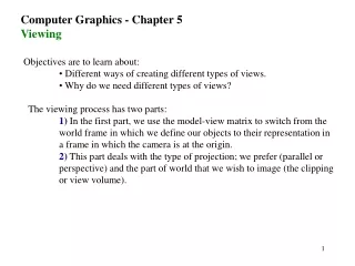
Computer Graphics Chapter FIVE THE VIEWING PIPLINE
Topics we will cover • The 3-D Graphics Viewing Pipeline • The Modelling Transformation • The Viewing Transformation • The Projection Transformation • Normalisationand Clipping • The Viewport Transformation • The OpenGL Viewing Pipeline • The Modelview Matrix • The Projection Matrix • The Viewport Matrix
The 3-D Graphics Viewing Pipeline • The viewing pipeline is a sequence of transformations that every primitive must undergo in order to be displayed. • In general terms, the viewing pipeline consists of the following transformations: • The Modelling Transformation • The Viewing Transformation • The Projection Transformation • Normalizationand Clipping • The Viewport Transformation • Every transformation can be thought of as defining a new coordinate system.
The Viewing Pipeline Figure - The 3-D Graphics Viewing Pipeline
1. The Modelling Transformation • Modeling refers to the process of building our 3-D scene from a number of basic primitives. • The modeling transformation is used to transform primitives relative to each other to form a 3-D scene. • After the modeling transformation all primitives are inworld coordinates.
The Modelling Transformation Figure - The Modelling Transformation
2. The Viewing Transformation • The viewing transformation represents the positioning, direction and orientation of the virtual camera that will take the picture of the scene. • After the viewing transformation all primitives are in viewing coordinates.
The Viewing Transformation Figure - The Viewing Coordinate System: the virtual camera ‘looks’ along the z-axis and the y-axis is ‘up’.
3. The Projection Transformation • The projection transformation projects3-D points onto a 2-D image plane. • After projection the primitives are in projection coordinates.
The Projection Transformation Figure - The Projection Transformation
The Projection Types • Projection transformations can be: • Parallel projections or • Perspective projections • Parallel projections can be: • Orthogonal (orthographic) or • Oblique parallel projections.
4. Normalisation and Cliping • The normalization and clipping transformation normalizes the view volume of the projection. • Decide which primitives (or parts of primitives) are ‘inside’ the picture and which ones are ‘outside’. In computer graphics, this process is known as clipping. • i.e. Scales coordinates to the range [0,1] or [-1,1]. • After this transformation the primitives are in normalised coordinates.
Normalisation and Cliping Figure - Near and Far Clipping Planes
The View Volume of the Projection • Different types of projection transformation lead to different shapes of view volume: • Using a perspective projection forms a view volume in the shape of a frustum. • A parallel (orthographic) projection leads to a view volume that is a cuboid (a 3-D rectangle).
5. The Viewport Transformation • The viewport transformation maps normalised coordinates to device coordinates. • This involves drawing the projected primitives onto a viewport of the screen window.
The Viewport Transformation Figure - The Viewport Transformation
The OpenGL Viewing Pipeline • OpenGL defines 3 matrices in its viewing pipeline. • Matrices are: • The Modelview Matrix • This matrix combines the effects of the modelling and viewing transformations in the general graphics pipeline. • The Projection Matrix • This represents the projection of 3-D viewing coordinate onto the image plane. • The Viewport Matrix • This matrix defines the part of the display that will be used for drawing.
1. The Model view Matrix • In OpenGL, the modelling and viewing transformations are combined into a single matrix: the modelview matrix. • glMatrixMode(GL_MODELVIEW); • Now we can use any of the following OpenGL functions to modify the current modelview matrix: • glTranslate* • glRotate* • glScale* • glLoadMatrix* • glMultMatrix* • gluLookAt Used to define the modelling part of the modelview matrix. Used to define the viewing part of the transformation.
gluLookAt • This function is used to define the viewing part of the transformation. • Recall that the viewing transformation defines the position, direction and orientation of a virtual camera. • The basic format of gluLookAt is as follows: • For example, the following 3 lines define a virtual camera positioned at (8, 0, 8) in world coordinates, looking at the origin, and with the y-axis as ‘up’.
2. The Projection Matrix • In OpenGL, theprojection transformation is represented by the projection matrix. • glMatrixMode(GL_PROJECTION); • Depending on the type of projection required, OpenGL provides 4 alternative functions for specifying the projection matrix: • gluOrtho2D • glOrtho • gluPerspective • glFrustum Used for specifying orthographic parallel projections. Used for specifying perspective projections.
gluOrtho2D • The gluOrtho2D function is intended for use with 2-D graphics only, • It does not allow you to specify near and far clipping planes. • The basic format of gluOrtho2D is: • For example, the lines of code shown below define a 2-D orthographic projection that will display all primitives with x-coordinate between 0 and 640, and y-coordinate between 0 and 480.
glOrtho • This is very similar to gluOrtho2D except that, • It allows us to specify near and far clipping planes, in addition to the left, right, bottom and top ones. • The basic format is: • For example, the following code specifies an orthographic projection that defines a view volume that is a 24x24x30 cuboid.
gluPerspective • The basic format is: • Here, theta represents the height angle of the perspective projection. • The next argument, aspect, is the aspect ratio of the image (the ratio of the width to the height). • The last two arguments, dnear and dfar, are the z-coordinates of the near and far clipping planes. • For example,
glFrustum • The basic format is: • Here, the first 4 arguments are the x and y coordinates of the left, right, bottom and top clipping planes at the near clipping plane. • The last two arguments, dnear and dfar, are the z-coordinates of the near and far clipping planes. • For example,
3. The Viewport Matrix • In OpenGL, the viewport transformation is represented by the viewport matrix. • The OpenGL viewport matrix can be defined using the glViewport function. • glViewport(xmin, ymin, xsize, ysize); • Here, (xmin, ymin) is the bottom-left corner of the viewport and the arguments xsize and ysize are the size of the viewport in pixels. • For example,