WIRE STRIKE PREVENTION
WIRE STRIKE PREVENTION. INTRODUCTION. Types of hazards Wire design WSPS and ability to cut Army guidance Important avoidance factors Wire hazard recons Night limitations Safety center accidents Summary. PURPOSE.

WIRE STRIKE PREVENTION
E N D
Presentation Transcript
WIRE STRIKE PREVENTION
INTRODUCTION Types of hazards Wire design WSPS and ability to cut Army guidance Important avoidance factors Wire hazard recons Night limitations Safety center accidents Summary
PURPOSE • Discuss methods and procedures to be followed while conducting operations in the terrain flight envelope, to include mission planning, briefing, in-flight operations and post mission responsibilities
OBJECTIVES • Understand capabilities of WSPS • Understand individual responsibilities to prevent wire strikes • Know procedures for pre-mission planning briefings, in-flight coordination and post mission actions to prevent wire strikes
OBJECTIVES • Increase aircrew awareness of the potential for mishaps if proper procedures are not followed
TYPES OF HAZARDS • Physical • Natural • Birds, trees, etc. • Manmade • Towers, wires, buildings • Weather • Haze, fog, precipitation, low sun • Human • Poor physical condition • Limited PERPHERAL vision • Fatigue • Attitude
TYPES OF WIRES • Tow missile wires • Guy wires • Fence lines • COMMO wires strung through trees • Power lines
Wire System Design • Voltage dictates the size of the wire. • Size varies from 1/4 inch to over 2 inches. • Large wires can carry 138,000 volts. • Most common size is about 1 inch. • Tensile strength is 18,000 lbs.
Wire System DesignedTo Withstand • Ice & wind - designed to allow the wire to stretch due to ice, wind, and temperature. • Wires can stretch from a few inches to six feet or more.
Guy Wires • Run horizontally from pole to pole or • diagonally from the pole to the ground. • Usually 3/4 to 1 inch in diameter (about the size of a nickel). • Tensile strength of over 50,000 lbs.
Power Lines In Local Flying Area • Aluminum cable • Being replaced • Copper cables • Range in size from .25 inches to 1 inch • Many of the cables being replaced are going underground
WSPS • The system consists of nine cutters/deflectors located on the fuselage and landing gear/support. • They are: • Upper cutter on the rear of the sliding fairing • Pitot cutter/deflector on the front of the sliding fairing • Windshield post wiper deflectors • Door hinge deflector • Step extension • Step deflector • Landing gear joint deflector • Main landing gear cutter/deflector • Tail landing gear deflector.
ARMY GUIDANCE ATM • Locate and accurately estimate the height of wires. • Determine the best method to negotiate the wire obstacles. • Safely negotiate the wire obstacle, minimizing the time unmasked. • Correctly perform crew coordination actions. STANDARDS
ATM DESCRIPTION TASK 2083 Negotiate wire obstacles. DESCRIPTION: 1. Crew actions. a. The P* will remain focused primarily outside the aircraft. b. The P and NCM will announce adequate warning to avoid hazards, wires, and poles or supporting structures. They also will announce when the aircraft is clear and when their attention is focused inside the aircraft. 2. Procedures. a. Announce when wires are seen. Confirm the location of wire obstacles with other crew members. b. Discuss the characteristics of wires and accurately estimate the amount of available clearance between them and the ground to determine the method of crossing. Locate guy wires and supporting poles. c. Announce the method of negotiating the wires and when the maneuver is initiated. Before crossing the wires, identify the highest wire. Cross near a pole to aid in visual perception and minimize the time that the aircraft is unmasked. When underflying wires, maintain a minimum clearance of hover height plus 30 feet and ground speed no greater than that of a brisk walk. Ensure lateral clearance from guy wires and poles. NOTE: The crew must maintain proper scanning techniques to ensure obstacle avoidance and aircraft clearance.
ATM NIGHT AND NVD CONSIDERATIONS • Crew should not perform task unless location is checked during daylight. • Wires are difficult to detect with NVG.
IMPORTANT FACTORS • Be aware of your attitude toward terrain flight • Physical conditioning and fatigue • Check hazards map • Brief other crewmember • Use proper visual scanning techniques and interpret visual cues • Birds roosting in midair • Long linear openings in wooded area • Poles • Areas around buildings
IMPORTANT FACTORS • Know location of aircraft at all times. • While in formation, stack up. • Be aware of and recognize existing blind spots. • When low, go slow. • IP’S, reinforce wire strike prevention. • Crew coordination • Don’t take shortcuts or violate procedures.
IMPORTANT FACTORS • Supervision - chain of command must enforce that pilots adhere to established procedures. • All aircraft in flight must know their position. • Minimize contour flight.
WIRE HAZARD RECONS • Schedule recons without incorporating into another mission • Flight Operations updates hazards maps
Airspeed and ground speed limitations Atmospheric conditions Object acquisition and identification Proficiency Humidity Obscurants
Associate wires with man-made features because they are difficult to see at night Long linear openings in a wooded area Poles Open areas near buildings NOE routes
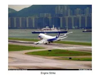
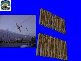
HISTORY OF WIRE STRIKES
HISTORY OF WIRE STRIKES • MEDEVAC aircraft responding to report of an “urgent surgical” patient did not have access to a hazard map of the area. Struck wires at approximately 50 to 55 feet. Aircraft was destroyed, and the three crewmembers were fatally injured.
HISTORY OF WIRE STRIKES
HISTORY OF WIRE STRIKES • Continuation/RL Progression NVG training mission. Crew selected a different route than the one that had been reconned earlier in the day. Struck a cable at approximately 40 feet AGL and 40 Kts. Main rotor blades contacted cable. Stabilator struck the riverbed, A/C settled into the river on its left side. Severe A/C damage, crew suffered minor injuries
During a night, unaided, multi-aircraft formation flight into obvious decreasing weather conditions, chalk 7 struck a set of high-tension wires twice at about 60 feet AGL. The first strike occurred going west as the pilot on the controls initiated a descent to a selected, immediate landing AH-64A 1 Mar 97 Night Ft. Hood, TX.
area to ensure safe separation from chalk 6. The second wire strike occurred after the PC took over the flight controls with the intent to land the windscreen damaged aircraft. The second wire strike occurred with the aircraft going generally east, approximately 3/4 mile south of the initial wire strike area. The tail rotor separated from the airframe in the second wire strike and the aircraft crashed out of control. The aircraft sustained major damage and the two pilots received minor injuries.
AH-64D 2 Oct 99 Night Bowie, TX. • While conducting NOE training mission, aircraft struck approximately 50’ telephone wire. PC felt a tug on the aircraft and landed aircraft suspecting wire strike. Maintenance inspection revealed no damage.
AH-64A 4 Dec 99 Night Bondsteel, Serbia • During contour flight in mountainous terrain, Apache contacted triple strand power lines (approximately 3/4 inch aluminum wire) The aircraft’s WSPS severed two strands of wire and the aircraft missed.
RIGHT MOST POLE ON FINAL APPROACH PATH AIRCRAFT LOCATION AFTER WIRE-STRIKE
AIRCRAFT WIRE THAT WAS STRUCK (ALREADY REPLACED)
LEFT MOST POLE ON APPROACH AIRCRAFT
RIGHT MOST POLE ON APPROACH AIRCRAFT
Final Thought • No one is immune to accidents. Experience, rank and age DO NOT create an error free aviator. Only diligence and compliance with established procedures in mission planning and execution will reduce or eliminate wire strike mishaps.
Summary Types of hazards Wire design WSPS and ability to cut Army guidance Important avoidance factors Wire hazard recons Night limitations Safety center accidents