Download
1 / 1
10 likes | 163 Views
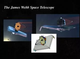
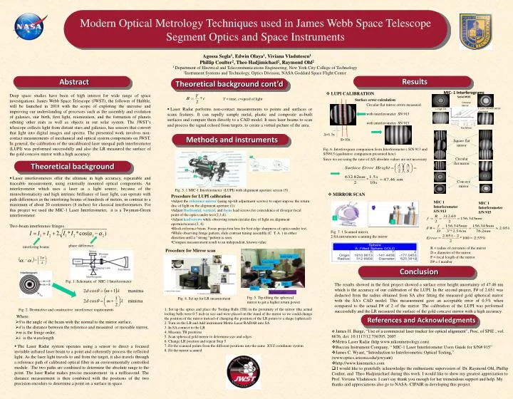
MIC- 1 Interferograms Serial #915. Modern Optical Metrology Techniques used in James Webb Space Telescope Segment Optics and Space Instruments. Square flat mirror. Laser radar. Concave Mirror. Laser beam. 2. Less Tilt with better alignment. 1. High Tilt. Spherical mirror.

E N D
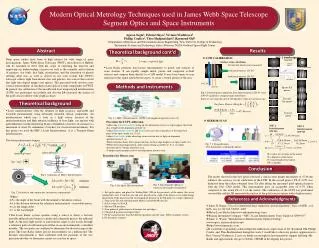
MIC- 1 Interferograms Serial #915 Modern Optical Metrology Techniques used in James Webb Space Telescope Segment Optics and Space Instruments Square flat mirror Laser radar Concave Mirror Laser beam 2. Less Tilt with better alignment 1. High Tilt Spherical mirror Circular flat mirror Agossa Segla1, Edwin Olaya1, Viviana Vladutescu1Phillip Coulter2, Theo Hadjimichael2, Raymond Ohl2 TB#3 Flat Mirror 1 Department of Electrical and Telecommunications Engineering, New York City College of Technology 2Instrument Systems and Technology, Optics Division, NASA Goddard Space Flight Center TB#2 TB#1 Fig. 5. Tip-tilting the spherical mirror to get a higher return power Results Abstract Theoretical background cont’d Reference points Concave mirror MIC 1 Interferometer S/N 913 • LUPI CALIBRATION Procedure for Mirror scan MIC 1 Interferometer S/N 915 Deep space studies have been of high interest for wide range of space investigations. James Webb Space Telescope (JWST), the follower of Hubble, will be launched in 2018 with the scope of exploring the universe and improving our understanding of processes such as the assembly and evolution of galaxies, star birth, first light, reionization, and the formation of planets orbiting other stars as well as objects in our solar system. The JWST’s telescope collects light from distant stars and galaxies, has sensors that convert that light into digital images and spectra. The presented work involves non-contact measurements of mechanical and optical system components on JWST. In general, the calibration of the uncalibrated laser unequal path interferometer (LUPI) was performed successfully and also the LR measured the surface of the gold concave mirror with a high accuracy. Surface error calculation Circular flat mirror errors measured with interferometer SN 913 with interferometer SN 915 Δ=1.5x Methods and instruments S=10x Fig. 4. Set up for LR measurement T = time, c=speed of light Fig. 6. Interferogram comparison from Interferometer s S/N 913 and S/N915 (qualitative comparison presented here) • Laser Radar performs non-contact measurements to points and surfaces or scans features. It can rapidly sample metal, plastic and composite as-built surfaces and compare them directly to a CAD model. It uses laser beams to scan and process the signal echoed from targets, to create a virtual picture of the area. 5 Since we are using the ratio of Δ/S absolute values are not necessary 2 Theoretical background 1 3 • Laser interferometers offer the ultimate in high accuracy, repeatable and traceable measurement, using externally mounted optical components. An interferometer which uses a laser as a light source; because of the monochromaticity and high intrinsic brilliance of laser light, can operate with path differences in the interfering beams of hundreds of meters, in contrast to a maximum of about 20 centimeters (8 inches) for classical interferometers. For this project we used the MIC-1 Laser Interferometer, it is a Twyman-Green interferometer. Two-beam interference fringes 4 Fig. 3. 1 MIC-1 Interferometer (LUPI) with alignment aperture screen (5) • MIRROR SCAN • Procedure for LUPI calibration • Adjust the reference mirror (using tip-tilt adjustment screws) to super-impose the return disc of light on the alignment aperture (1). • Adjust Horizontal, vertical, and focus lead screws for coincidence of diverger focal point of the optics under test (2,3,4). • Adjust lead screws while observing return circular disc of light on alignment aperture/screen (3, 4). • Block reference beam. Focus projection lens for best edge sharpness of optics under test. • While observing fringe pattern, slide contrast tuning assembly (C. T. A. ) in either direction until a “strong “pattern is seen. • Compare measurement result to an independent, known value 1 2 Fig. 7. 1 Scanned mirror, 2 SA instruments scanning the mirror R = radius of curvature of the mirror D = diameter of the mirror F = focal length of the mirror F# = f number Conclusion The results showed in the first project showed a surface error height uncertainty of 47.46 nm which is the accuracy of our calibration of the LUPI. In the second project, F# of 2.051 was deducted from the radius obtained from SA after fitting the measured gold spherical mirror with the SA's CAD model. This measurement gave an acceptable error of 0.5% when compared to the actual F# of 2 of the mirror. The calibration of the LUPI was performed successfully and the LR measured the surface of the gold concave mirror with a high accuracy. interfering beams phase difference 1. Set up the optics and place the Tooling Balls (TB) in the proximity of the mirror (the actual tooling balls were 0.5 inch in size and were placed on the stand of the mirror so we could change the position of the mirror instead of changing the position of the LR points to a shape (spherical) 2. Turn on the LR and Add instrument Metris Laser RADAR into SA 3. In SA connect to the LR 4. Measure TB positions 5. Scan spherical gold mirror to determine size and edges 6. Change LR position and repeat Step 5 7. Fit the scanned points from the different positions into the same XYZ coordinate system 8. Fit the mirror scanned • Where: • θis the angle of the beam with the normal to the mirror surface, • d is the distance between the reference and measured or movable mirror, • m is the fringe order • λis the wavelength References and Acknowledgments • James H. Burge, “Use of a commercial laser tracker for optical alignment”, Proc. of SPIE , vol. 6676, doi: 10.1117/12.736705, 2007 • Metris Laser Radar (http:www.nikonmetrology.com) • Buccini Instrument Company, “ MIC-1 Laser Interferometer Users Guide for S/N# 915” • James C. Wyant, “Introduction to Interferometric Optical Testing,” (www.optics.arizona.edu/jcwyant) • http://www.kinematics.com • I would like to gratefully acknowledge the enthusiastic supervision of Dr. Raymond Ohl, Phillip Coulter, and Theo Hadjimichael during this work. I would like to show my greatest appreciation to Prof. VivianaVladutescu. I can't say thank you enough for her tremendous support and help. My thanks and appreciations also go to NASA- CIPAIR in developing this project. Fig. 1. Schematic of MIC-1 Interferometer • The Laser Radar system operates using a sensor to direct a focused invisible infrared laser beam to a point and coherently process the reflected light. As the laser light travels to and from the target, it also travels through a reference path of calibrated optical fiber in an environmentally controlled module. The two paths are combined to determine the absolute range to the point. The laser Radar makes precise measurement in a millisecond. The distance measurement is then combined with the positions of the two precision encoders to determine a point on a surface in space. Fig. 2. Destructive and constructive interference requirements