Download
1 / 32
320 likes | 378 Views
Learn how to position, orient, and project objects in a scene using OpenGL transformations. Explore matrix operations, clipping, and mapping to create captivating visual displays. Dive into vertex transformation stages and practical cube drawing examples.

E N D
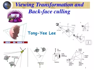
Transformation and Viewing in OpenGL 168 471 Computer Graphics, KKU. Lecture 13
Scenario: • We want to make sure that • The final image of the scene contains a good view. • The portion of the floor is visible. • All objects in the scene are visible. • All objects in the scene are presented in an interesting arrangement. • Questions • How to position the models? • How to orient the models? • How to establish the location of the viewpoint? • Note: all tasks have to happen in three space. 168 471 Computer Graphics, KKU. Lecture 13
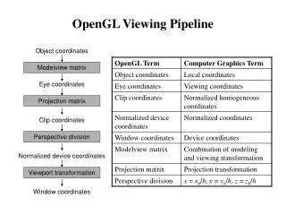
Series of Operations • There are 3 computer operations that convert an object’s 3D coordinates to pixel position on the screen. • Matrix Multiplications: Transformations (modeling, viewing and projection) to roate, scale, reflect, orthographically project and perspectively project. Generally, we use a combination of several of these. • Clipping operation: throw out objects that lie outside the area or volume. • Mapping operation: established between the transformed coordinates and pixels. This is known as a Viewport transformations 168 471 Computer Graphics, KKU. Lecture 13
The Camera Analogy • To take a photograph with a camera, steps might be • Set up your tripod and pointing the camera at the scene (viewing trans.) • Arrange the scene to be photographed into the desired composition (modoling trans.) • Choose a camera lens or adjust the zoom (projection trans.) • Determine how large you want the final photograph to be - for example, you might want it enlarged (viewport trans.) • After these steps are performed, the picture can be snapped or the scene can be drawn. 168 471 Computer Graphics, KKU. Lecture 13
Stages of Vertex Transformation • Modelview matrix: orients the model and the camera relative to each other. • Projection matrix: specifies the shape and orietation of the viewing volume. • Viewport transformation: controls the conversion of 3D model coordinates to screen coordinates. 168 471 Computer Graphics, KKU. Lecture 13
Example: Drawing Cube #include <GL/gl.h> #include <GL/glu.h> #include <GL/glut.h> void init(void) { glClearColor (0.0, 0.0, 0.0, 0.0); glShadeModel (GL_FLAT); } void display(void) { glClear (GL_COLOR_BUFFER_BIT); glColor3f (1.0, 1.0, 1.0); glLoadIdentity (); /* clear the matrix */ /* viewing transformation */ gluLookAt (0.0, 0.0, 5.0, 0.0, 0.0, 0.0, 0.0, 1.0, 0.0); glScalef (1.0, 2.0, 1.0); /* modeling transformation */ glutWireCube (1.0); glFlush (); } 168 471 Computer Graphics, KKU. Lecture 13
Example: Drawing Cube (cont.) void reshape (int w, int h) { glViewport (0, 0, (GLsizei) w, (GLsizei) h); glMatrixMode (GL_PROJECTION); glLoadIdentity (); glFrustum (-1.0, 1.0, -1.0, 1.0, 1.5, 20.0); glMatrixMode (GL_MODELVIEW); } int main(int argc, char** argv) { glutInit(&argc, argv); glutInitDisplayMode (GLUT_SINGLE | GLUT_RGB); glutInitWindowSize (500, 500); glutInitWindowPosition (100, 100); glutCreateWindow (argv[0]); init (); glutDisplayFunc(display); glutReshapeFunc(reshape); glutMainLoop(); return 0; } 168 471 Computer Graphics, KKU. Lecture 13
Example: Drawing Cube (cont.) • Viewing Transformation • Analogus to positioning and aiming the camera. • Usage: gluLookAt() • Arguments indicate where the camera (eye position) is placed, where it is aimed, and which way is up. • In the example, we place the camera at (0, 0, 5), aim the camera lens toward (0, 0, 0) and specify the up-vector as (0, 1, 0) • By default the camera is at the origin (0, 0, 0), points down the negative z-axis and has an up-vector of (0, 0, 1) • Modeling Transformation • Analogous to positioning and orienting the model. • Uasge: glScalef() • Arguments specify how scaling should occur along the 3 axes. • In the example, the cube is drawn twice as large in the y direction What about using glTranslatef(0, 0, 5) instead of gluLookAt()? 168 471 Computer Graphics, KKU. Lecture 13
Example: Drawing Cube (cont.) • Projection Transformation • Similar to choosing a lens for a camera as determining what the field of view (FOV) or viewing volume is. • In addition, it determines how objects are projected onto screen. • Usage: glFrustum() • Arguments describe values of left, right, bottom, top, near and far for a viewing volume. • Before calling glFrustum(), glMatrixMode() with the argument GL_PROJECTION must be called. • After calling glFrustum(), the matrix stack must be set back to GL_MODELVIEW • Take care the current matrix with glLoadIdentity() Note: Default matrix stack is GL_MODELVIEW 168 471 Computer Graphics, KKU. Lecture 13
Example: Drawing Cube (cont.) • Viewport Transformation • Indicates the region of available screen area into which the scene is mapped. • Usage: glViewport() • The arguments describe the origin, the width and height of the region within the window. • What does OpenGL do when all transformations have been specified? • Transforms each vertex of every object in the scene by the modeling and viewing transformations. • Transforms the vertices and clips the objects by the projection transformations • Divides the remaining transformed vertices with w and maps them onto the viewport. 168 471 Computer Graphics, KKU. Lecture 13
Let’s Think About Transformations • In general, the order of transformation is critical • If oyu do transformation A and then transformation B, you almost always get something different than you do them the the opposite order. 168 471 Computer Graphics, KKU. Lecture 13
Order of Transformations in OpenGL Consider the following code sequence, which draws a single point using three transformations: glMatrixMode(GL_MODELVIEW); glLoadIdentity(); glMultMatrixf(N); /* apply transformation N */ glMultMatrixf(M); /* apply transformation M */ glMultMatrixf(L); /* apply transformation L */ glBegin(GL_POINTS); glVertex3f(v); /* draw transformed vertex v */ glEnd(); • The modelview matrix successively contains I, N, NM and finally NML. • The transformed vertex is NMLv, equivalent to N(M(LvThe transformations to vertex v effectively occur in the opposite order than they were specified. • Actually, the N, M and L metrices are alrady multiplied into a single matrix before applied to v. 168 471 Computer Graphics, KKU. Lecture 13
Modeling Transformations 1. Translate • void glTranslate{fd}(TYPEx, TYPE y, TYPEz); • Multiplies the current matrix by a matrix that moves (translates) an object by the given x, y, and z values (or moves the local coordinate system by the same amounts). 168 471 Computer Graphics, KKU. Lecture 13
Modeling Transformations (cont.) 2. Rotate • void glRotate{fd}(TYPE angle, TYPE x, TYPE y, TYPE z); • Multiplies the current matrix by a matrix that rotates an object (or the local coordinate system) in a counterclockwise direction about the ray from the origin through the point (x, y, z). The angle parameter specifies the angle of rotation in degrees. glRotatef(45.0, 0.0, 0.0, 1.0), 168 471 Computer Graphics, KKU. Lecture 13
Modeling Transformations (cont.) 3. Scale • void glScale{fd}(TYPEx, TYPE y, TYPEz); • Multiplies the current matrix by a matrix that stretches, shrinks, or reflects an object along the axes. Each x, y, and z coordinate of every point in the object is multiplied by the corresponding argument x, y, or z. With the local coordinate system approach, the local coordinate axes are stretched, shrunk, or reflected by the x, y, and z factors, and the associated object is transformed with them. glScalef(2.0, -0.5, 1.0) Note: A scale value of zero collapses all objects coordinates along that axis to zero 168 471 Computer Graphics, KKU. Lecture 13
Viewing Transformations A viewing transformation changes the position and orientation of the viewpoint. • void gluLookAt(GLdouble eyex, GLdouble eyey, GLdouble eyez, GLdouble centerx, GLdouble centery, GLdouble centerz, GLdouble upx, GLdouble upy, GLdouble upz); • Defines a viewing matrix and multiplies it to the right of the current matrix. The desired viewpoint is specified by eyex, eyey, and eyez. The centerx, centery, and centerz arguments specify any point along the desired line of sight, but typically they're some point in the center of the scene being looked at. The upx, upy, and upz arguments indicate which direction is up (that is, the direction from the bottom to the top of the viewing volume). 168 471 Computer Graphics, KKU. Lecture 13
Viewing Transformations (cont.) Default camera position gluLookAt(4.0, 2.0, 1.0, 2.0, 4.0, -3.0, 2.0, 2.0, -1.0); 168 471 Computer Graphics, KKU. Lecture 13
Viewing Transformations (cont.) • Remember that you can manufacture a view transformation in any of several ways. • Use one or more modeling transformation commands (that is, glTranslate*() and glRotate*()). You can think of the effect of these transformations as moving the camera position or as moving all the objects in the world, relative to a stationary camera. • Use the Utility Library routine gluLookAt() to define a line of sight. This routine encapsulates a series of rotation and translation commands. • Create your own utility routine that encapsulates rotations and translations. 168 471 Computer Graphics, KKU. Lecture 13
Projection Transformations The purpose of the projection transformation is to define a viewing volume. There are 2 types of projections: • Perspective projection • Orthographic projection Remember that before you issue any of the projection transformation commands, you must call glMatrixMode(GL_PROJECTION); glLoadIdentity(); 168 471 Computer Graphics, KKU. Lecture 13
Perspective Projection • void glFrustum(GLdouble left, GLdouble right, GLdouble bottom,GLdouble top, GLdouble near, GLdouble far); • Creates a matrix for a perspective-view frustum and multiplies the current matrix by it. The frustum's viewing volume is defined by the parameters: (left, bottom, -near) and (right, top, -near) specify the (x, y, z) coordinates of the lower-left and upper-right corners of the near clipping plane; near and far give the distances from the viewpoint to the near and far clipping planes. They should always be positive. 168 471 Computer Graphics, KKU. Lecture 13
Perspective Projection (cont.) • void gluPerspective(GLdouble fovy, GLdouble aspect, GLdouble near, GLdouble far); • Creates a matrix for a symmetric perspective-view frustum and multiplies the current matrix by it. fovy is the angle of the field of view in the x-z plane; its value must be in the range [0.0,180.0]. aspect is the aspect ratio of the frustum, its width divided by its height. near and far values the distances between the viewpoint and the clipping planes, along the negative z-axis. They should always be positive. 168 471 Computer Graphics, KKU. Lecture 13
Orthographic Projection • void glOrtho(GLdouble left, GLdouble right, GLdouble bottom, GLdouble top, GLdouble near, GLdouble far); • Creates a matrix for an orthographic parallel viewing volume and multiplies the current matrix by it. (left, bottom, -near) and (right, top, -near) are points on the near clipping plane that are mapped to the lower-left and upper-right corners of the viewport window, respectively. (left, bottom, -far) and (right, top, -far) are points on the far clipping plane that are mapped to the same respective corners of the viewport. Both near and far can be positive or negative. 168 471 Computer Graphics, KKU. Lecture 13
Orthographic Projection (cont.) • void gluOrtho2D(GLdouble left, GLdouble right, GLdouble bottom, • GLdouble top); • Creates a matrix for projecting two-dimensional coordinates onto the screen and multiplies the current projection matrix by it. The clipping region is a rectangle with the lower-left corner at (left, bottom) and the upper-right corner at (right, top). 168 471 Computer Graphics, KKU. Lecture 13
Viewport Transformation The viewport transformation specifies the rectangular region of the window where the model is drawn. • void glViewport(GLint x, GLint y, GLsizei width, GLsizei height); • Defines a pixel rectangle in the window into which the final image is mapped. The (x, y) parameter specifies the lower-left corner of the viewport, and width and height are the size of the viewport rectangle. By default, the initial viewport values are (0, 0, winWidth, winHeight), where winWidth and winHeight are the size of the window. 168 471 Computer Graphics, KKU. Lecture 13
Viewport Transformation (cont.) The aspect ratio of a viewport should generally equal to the aspect ratio of the viewing volume. gluPerspective(fovy, 1.0, near, far); glViewport(0, 0, 400, 400); gluPerspective(fovy, 1.0, near, far); glViewport (0, 0, 400, 200); 168 471 Computer Graphics, KKU. Lecture 13
Matrix Stacks • OpenGL supports two stacks of matrices • Modelview matrix stack (32 4x4 matrices) • Projection matrix stack (2 4x4 matrices) • These stacks are useful for constructing hierarchical models. For example a car made of its body and the four wheels: Rotate wheels Rotate wheels + Rotate body 168 471 Computer Graphics, KKU. Lecture 13
Matrix Stacks • glPushMatrix(void) - Pushes all matrices in the current stack down one level. • glPopMatrix(void) - Pops the top matrix off the current stack, losing the topmost matrix! • (The current stack is determined by glMatrixMode). Current matrix level M4 M3 M2 M1 M4 M4 M3 M2 M1 Push M5 Current matrix level M4 M3 M2 M1 M5 M4 M3 M2 M1 Pop 168 471 Computer Graphics, KKU. Lecture 13
Matrix Stacks • Example code: void drawCar() { glMatrixMode(GL_MODELVIEW) ; glTranslatef(x,y,z) ; /*/ glRotatef(car_ang, 0, 1, 0) ; /*/ draw_car_body() ; glPushMatrix() ; glTranslate(-1,0,1) ; glRotatef(wheels_ang, 0, 1, 0) ; draw_car_wheel() ; glPopMatrix() ; glPushMatrix() ; glTranslate(1,0,1) ; glRotatef(wheels_ang, 0, 1, 0) ; draw_car_wheel() ; glPopMatrix() ; } • First we move and rotate the car (body + wheels) - as it is the top level in the hierarchy. • Next we push the stack - and therefore store a copy. • Then we draw the right and left wheels in their appropriate position and orientation. Note that on each wheel the transformation /*/ will operate. • The last pop will retrieve the matrix containing only the /*/ transformations. 168 471 Computer Graphics, KKU. Lecture 13
Additional Clipping Planes • void glClipPlane(GLenum plane, const GLdouble *equation); • Defines a clipping plane. The equation argument points to the four coefficients of the plane equation, Ax+By+Cz+D = 0. All points with eye coordinates (xe, ye, ze, we) that satisfy (A B C D)M-1 (xe ye ze we)T >= 0 lie in the half-space defined by the plane, where M is the current modelview matrix at the time glClipPlane() is called. All points not in this half-space are clipped away. The plane argument is GL_CLIP_PLANEi, where i is an integer specifying which of the available clipping planes to define. i is a number between 0 and one less than the maximum number of additional clipping planes. Each plane is specified by the coefficients of its equation: Ax+By+Cz+D = 0. 168 471 Computer Graphics, KKU. Lecture 13
Global and Local Frames In summary, these are the OpenGL commands to draw the sun and planet glPushMatrix(); glutWireSphere(1.0, 20, 16); /* draw sun */ glRotatef ((GLfloat) year, 0.0, 1.0, 0.0); glTranslatef (2.0, 0.0, 0.0); glRotatef ((GLfloat) day, 0.0, 1.0, 0.0); glutWireSphere(0.2, 10, 8); /* draw smaller planet */ glPopMatrix(); 168 471 Computer Graphics, KKU. Lecture 13
Global and Local Frames void keyboard (unsigned char key, int x, int y) { switch (key) { case `d': day = (day + 10) % 360; glutPostRedisplay(); break; case `D': day = (day - 10) % 360; glutPostRedisplay(); break; case `y': year = (year + 5) % 360; glutPostRedisplay(); break; case `Y': year = (year - 5) % 360; glutPostRedisplay(); break; default: break; } } int main(int argc, char** argv) { glutInit(&argc, argv); glutInitDisplayMode (GLUT_DOUBLE | GLUT_RGB); glutInitWindowSize (500, 500); glutInitWindowPosition (100, 100); glutCreateWindow (argv[0]); init (); glutDisplayFunc(display); glutReshapeFunc(reshape); glutKeyboardFunc(keyboard); glutMainLoop(); return 0; } #include <GL/gl.h> #include <GL/glu.h> #include <GL/glut.h> static int year = 0, day = 0; void init(void) { glClearColor (0.0, 0.0, 0.0, 0.0); glShadeModel (GL_FLAT); } void display(void) { glClear (GL_COLOR_BUFFER_BIT); glColor3f (1.0, 1.0, 1.0); glPushMatrix(); glutWireSphere(1.0, 20, 16); /* draw sun */ glRotatef ((GLfloat) year, 0.0, 1.0, 0.0); glTranslatef (2.0, 0.0, 0.0); glRotatef ((GLfloat) day, 0.0, 1.0, 0.0); glutWireSphere(0.2, 10, 8); /* draw smaller planet */ glPopMatrix(); glutSwapBuffers(); } void reshape (int w, int h) { glViewport (0, 0, (GLsizei) w, (GLsizei) h); glMatrixMode (GL_PROJECTION); glLoadIdentity (); gluPerspective(60.0, (GLfloat) w/(GLfloat) h, 1.0, 20.0); glMatrixMode(GL_MODELVIEW); glLoadIdentity(); gluLookAt (0.0, 0.0, 5.0, 0.0, 0.0, 0.0, 0.0, 1.0, 0.0); } 168 471 Computer Graphics, KKU. Lecture 13