Download
1 / 8
0 likes | 13 Views
Proco Products, Inc. is the global leader in the design and supply of expansion joints for piping and ducting systems.

E N D
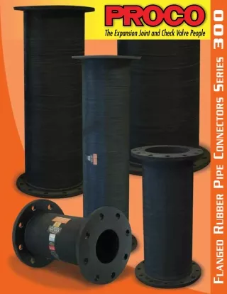
Proco Series 300 Flagged Rubber Pipe Connectors PROCO Series 300 Rubber Pipe is designed for tough demanding industrial and commercial applications as found in: Chemical-Petrochemical and Industrial Process Piping Systems, Power Generating Plants, Steel Mills, Marine Services, Pulp/Paper Systems, Water-Waste/Water-Sewage and Pollution Control Systems. Specific equipment applications could include: Pumps, Cooling Towers, Compressors, Blowers, Fans, Absorption Machines, etc. Installed next to mechanical equipment or between the anchor points of a piping system, specify the PROCO Series 300 to: (1) Isolate Mechanical Vibration, (2) Reduce System Noise, (3) Absorb Pipe Movement/Stress, (4) Compensate Alignment/Offset, (5) Eliminate Electrolysis, (6) Protect Against Start-Up/Surge Forces. When you need an engineered rubber solution to a piping system problem, call PROCO. Engineered For Your Application. Each PROCO Series 300 Rubber Pipe is constructed with a smooth interior tube specially compounded from an elastomer that satisfies the Chemical-Abrasion-Sound requirements of your application (See Table 2). Multiple plies of tough fabric and helical spring steel wire are embedded into the pipe wall during the manufacturing process to provide a product designed for your pressure and vacuum requirements. Available styles include: Style 310-R: Precision molded to specific lengths as listed in Table 3. The built-in rubber flanges are drilled to ANSI - 125/150#. Style 310: Manufactured by conventional methods which allow for fabrication to a specific length requirement, in addition to lengths as shown in Table 3. Standard with 125/150# drilling, the Style 310 can also be fabricated to meet other drilling patterns. Style 320: Designed for high pressure applications (See Table 4); this connector manufactured similar to Style 310. Flanges are usually drilled to ANSI 250/300# with other drilling patterns furnished on request. Absorbs Pipe-Wall and Fluid-Borne Noise. The PROCO quiet-operating Series 300 is a replacement for “sound transmitting” metallic connectors. Compare the Acoustical Impedance ratings of rubber and other materials, as shown in Table 1. Pipe-Wall sound is absorbed as the noise carried by the piping both enters and leaves the rubber section. Connector length further influences absorption as sound loses energy traveling axially through the rubber. For optimum lengths, see Table 3. Fluid-borne noise is absorbed by the volumetric expansion (breathing) of the connector. This action cushions water hammer, and smoothes out pumping impulses. Isolate Vibrations and Motion. Vibration originating from mechanical equipment is absorbed by the PROCO Series 300. Rubber pipe connectors should be installed right after and ahead of the equipment generating the vibration, thus isolating the equipment. As most machinery vibrates in a radial direction from the main shaft, for optimum performance the pipe connector should be installed horizontally and parallel to this shaft. While PROCO Series 300 Rubber Pipe will accept some axial motion, it is principally designed to accept transverse motion. When installed at right angles to the direction of the pipe motion (movement), PROCO rubber pipe connectors can absorb large amounts of expansion. For major two-plane vibration/motion it is best to use two flexible rubber pipe connectors installed at right angles, one to absorb the horizontal vibration and one to absorb the vertical vibration. A tension anchor is usually advisable to stabilize the elbow between the connectors. Note: For maximum vibration transmission reduction, the piping section beyond the rubber connector must be anchored or sufficiently rigid. Prevents Electrolysis and Electrolytic Action. In chemical applications when metallic connectors are used, they are generally of a metal dissimilar from the pipe-line. This could create an electrolytic galvanic action that could be destructive to the connector, equipment or piping system. The use of the PROCO Series 300 eliminates this potential hazard. Additionally, because the all-rubber connector eliminates metal-to-metal contact at the flange face, electrolysis is stopped. Systems Misalignment Compensation. In a rigid piping system, the installation of the PROCO Series 300 Rubber Pipe adds a flexible component that is automatically selfcorrecting for misalignment created by structural movements caused by settling, expansion or ground shifts (See Table 3). Chemical Or Abrasive Service Capability At Minimal Cost: Expensive, exotic metal connectors for chemical service can be replaced with the PROCO Series 300. Fabricated with low cost chemical resistant elastomer such as: Chlorobutyl, EPDM, Gum, CSM, Neoprene and Nitrile; insures a rubber connector compatible with the fluid being pumped or piped (See Table 1). Our Gum or Neoprene products should be specified when handling abrasive slurries. Use PROCO “Chemical to Elastomer Guide” to specify an elastomer for your requirements. Protecting Piping & Equipment Systems From Stress/Motion sales@procoproducts.com • (800) 344-3246 1
Series 300 Performance Data Table 1: Comparison of Material Acoustical Impedances Sound Velocity In. / Sec. Steel Copper Cast Iron Lead Glass 216,000 .094 Concrete Water Pine Cork Rubber 2,400 .0442 Table 2: Available Styles and Materials For Specific Elastomer Recommendations, See:PROCO™ “Chemical To Elastomer Guide” PROCO Material Code * * * * * * * * * NP Neoprene Acoustical Impedance Lbs. / In.2 Sec. 58,440 44,930 38,690 20,470 20,300 14,260 2,030 1,910 Density Lbs./In.3 Relative Impedance Material Maximum Operating Temp °F 250° 250° 250° 180° 212° 225° 212° F.S.A. Material Class Special II Special II Special II Std. I Std. II Std. II Std. II Cover Elastomer Tube 310 310-R 320 .283 .320 .260 .411 551.3 423.9 365.0 193.1 191.5 134.5 19.2 18.0 1.6 1.0 206,500 140,400 148,800 49,800 Elastomer Chlorobutyl Teflon® EPDM Natural CSM Neoprene Nitrile Chlorobutyl Chlorobutyl EPDM Neoprene Neoprene Neoprene BB BT EE NR NH NN * * * * * * * 198,000 56,400 132,000 19,200 .072 .036 .0145 .0086 * * 165 106 Product “cover” can be CSM coated on special order. Style 310/NN meets ASTM, Class A. Type III and conforms to all USCG requirements. NOTES: Acoustical impedance is defined as the product of material density times velocity of sound in that material. In acoustical systems low impedance corresponds to low sound transmission. Relative impedance is based on Rubber = 1.0 NOTES: 1. Teflon is a registered trademark of the DuDont Company. 2. Products with Teflon® “tubes” are not recommended with vacuum service. Reduce System Stress And Strain. Rigid attachment of piping to critical or mechanical equipment can produce excessive loading. Thermal or mechanically created strain-stress-shock are cushioned and absorbed with the installation of a flexible PROCO Series 300 Rubber Pipe. Full Flow With Less Turbulence Or Material Entrapment. The smooth bore of the PROCO Series 300 Rubber Pipe Connector allows full flow without turbulence. Metallic connectors depend upon bellows or convolutions to absorb motion. These bellows/ convolutions could create flow turbulence and also create an area for material entrapment or bacteria growth. Leak Free Without Gaskets Or Packing. The full-face rubber flange of the PROCO Series 300 Rubber Pipe Connector is self gasketing. Additionally, the Style 310-R features a molded in place “O-Ring” on each flange-face for faster sealing with less torque at installation and less long-term maintenance. Unlike interlocked metallic connectors, the Series 300 features a onepiece seamless tube that does not require packing. Our rubber connector is suitable for all air, gas, and fluids, including “searching” thin fluids. Control Rod Assembly Usage. PROCO Style 491 Control Units are designed to protect the Series 300 Pipe Connector from excessive elongation. Control rods must be used: (1) when the piping containing the rubber pipe connector is not anchored and, (2) when the rubber pipe connector is attached to resiliently supported pipe or equipment. Force Required for Lateral Displacement Based on: 2.5” I.D. x 18” Length Product Pressure-Elongation Curve Based on: 2.5” I.D. x 18” Length Product 60 3 Load Required: Force in Pounds Percent of Elongation 40 2 20 1 .5” 1” 1.5” 2” 100 200 300 400 Total Lateral Movement Pressure in PSIG sales@procoproducts.com • (800) 344-3246 2
Series 300 Performance Data continued Table 3: Sizes • Movements • Flange Dimensions • Weights • Pressures Movement Capability From Neutral 125/150# Flange Dimensions Rubber Pipe Dimensions Approx. Weight (lbs) Operating Pressures3 Nominal Pipe Size: Pipe I.D. “A” Flange Thickness Retaining Rings (set) ± In. of Angular ± In. of Lateral Neutral Length Size of Holes Compression Style 310-R Style 310-R Flange O.D. In. of Axial In. of Axial “B” Body # of Holes Style 310 Style 320 Bolt Circle Deflection Deflection Extension Thickness 2.4 3.2 1.5 1.5 12* 18 .158 .236 .158 .236 1.97 2.96 21.8° 31.0° .75 3.875 2.750 4 0.625 0.591 0.472 3.3 4.2 1.9 1.9 12* 18 .158 .236 .158 .236 1.77 2.66 17.7° 25.6° 1 4.250 3.120 4 0.625 0.591 0.551 12* 18 24 .158 .236 .315 .158 .236 .315 1.58 2.36 3.15 14.0° 20.6° 26.6° 4.0 5.0 6.0 2.4 2.4 2.4 300 300 1.25 4.625 3.500 4 0.625 0.591 0.551 12* 18 24 .158 .236 .315 .158 .236 .315 1.39 2.09 2.78 11.3° 16.7° 21.8° 4.3 5.4 6.5 2.6 2.6 2.6 1.5 5.000 3.880 4 0.625 0.591 0.551 5.6 6.8 8.0 9.2 2.6 2.6 2.6 2.6 12* 18 24 30 .158 .236 .315 .354 .158 .236 .315 .354 1.18 1.77 2.36 2.96 9.1° 13.5° 17.7° 19.8° 2 250 6.000 4.750 4 0.750 0.591 0.551 6.9 8.2 9.5 10.0 5.3 5.3 5.3 5.3 12* 18 24 30 .158 .236 .315 .354 .158 .236 .315 .354 .98 1.48 1.97 2.46 7.0° 10.5° 13.8° 15.5° 2.5 200 7.000 5.500 4 0.750 0.591 0.551 12* 18 24 30 36 .158 .236 .315 .354 .433 .158 .236 .315 .354 .433 .79 1.18 1.58 1.97 2.36 5.7° 8.5° 11.3° 12.7° 15.4° 8.6 10.6 11.7 14.6 16.6 5.6 5.6 5.6 5.6 5.6 3 7.500 6.000 4 0.750 0.591 0.551 150 12 18* 24 30 36 .158 .236 .315 .354 .433 .158 .236 .315 .354 .433 .59 .89 1.18 1.48 1.77 5.1° 7.6° 10.1° 11.3° 13.7° 9.7 12.2 14.7 17.2 19.7 6.5 6.5 6.5 6.5 6.5 3.5 8.500 7.000 8 0.750 0.591 0.669 250 175 7.3 7.3 7.3 7.3 7.3 7.3 4.6° 6.8° 9.1° 10.2° 12.4° 14.8° 10.9 14.5 17.4 19.7 21.9 27.2 .59 .89 1.18 1.48 1.77 1.98 .158 .236 .315 .354 .433 .472 .158 .236 .315 .354 .433 .472 12 18* 24 30 36 48 4 9.000 7.500 8 0.750 0.591 0.669 12 18* 24 30 36 .158 .236 .315 .354 .433 .158 .236 .315 .354 .433 .45 .67 .89 1.12 1.34 3.7° 5.5° 7.3° 8.2° 10.0° 13.5 16.6 20.1 23.1 26.1 7.9 7.9 7.9 7.9 7.9 5 10.000 8.500 8 0.875 0.591 0.669 12 18 24* 30 36 48 .158 .236 .315 .354 .433 .472 .158 .236 .315 .354 .433 .472 .45 .67 .89 1.12 1.34 1.55 3.1° 4.6° 6.1° 6.8° 8.3° 9.9° 18.9 19.9 24.1 27.2 31.5 39.0 9.1 9.1 9.1 9.1 9.1 9.1 6 11.000 9.500 8 0.875 0.591 0.709 150 sales@procoproducts.com • (800) 344-3246 3
Table 3: Sizes • Movements • Flange Dimensions • Weights • Pressures Movement Capability From Neutral 125/150# Flange Dimensions Rubber Pipe Dimensions Approx. Weight (lbs) Operating Pressures3 Nominal Pipe Size: Pipe I.D. “A” Flange Thickness Retaining Rings (set) “B” Body Thickness ± In. of Angular ± In. of Lateral Neutral Length Size of Holes Compression Style 310-R Style 310-R Flange O.D. In. of Axial In. of Axial # of Holes Style 310 Style 320 Bolt Circle Deflection Deflection Extension 12 18 24* 30 36 48 .118 .158 .236 .276 .354 .472 .118 .158 .236 .276 .354 .472 .35 .53 .71 .89 1.06 1.42 1.7° 2.3° 3.4° 4.0° 5.1° 6.8° 23.4 29.4 35.7 40.2 47.4 59.4 14.0 14.0 14.0 14.0 14.0 14.0 8 13.500 11.750 8 0.875 0.591 0.787 12 18 24* 30 36 48 .118 .158 .236 .276 .354 .472 .118 .158 .236 .276 .354 .472 .32 .47 .63 .79 .95 1.26 1.4° 1.8° 2.7° 3.2° 4.1° 5.5° 26.0 37.0 48.7 59.0 70.0 92.0 17.0 17.0 17.0 17.0 17.0 17.0 10 16.000 14.250 12 1.000 0.787 0.866 150 150 250 12 18 24* 30 36 48 .118 .158 .236 .276 .354 .472 .118 .158 .236 .276 .354 .472 .24 .36 .47 .59 .71 .95 1.1° 1.5° 2.3° 2.7° 3.4° 4.2° 36.0 51.0 66.5 81.0 96.0 126.0 24.1 24.1 24.1 24.1 24.1 24.1 12 19.000 17.000 12 1.000 0.787 0.984 12 18 24* 30 36 48 .118 .158 .236 .276 .354 .472 .118 .158 .236 .276 .354 .472 .24 .36 .47 .59 .71 .95 1.0° 1.3° 2.0° 2.3° 2.9° 3.9° 58.0 83.0 108.0 133.0 157.0 208.0 26.8 26.8 26.8 26.8 26.8 26.8 14 21.000 18.750 12 1.125 0.787 0.984 125* 125 200 12 18 24* 36 48 .118 .158 .236 .354 .472 .118 .158 .236 .354 .472 .24 .36 .47 .71 .95 0.7° 1.3° 1.7° 2.6° 3.4° 83.0 118.0 153.0 233.0 294.0 32.1 32.1 32.1 32.1 32.1 16 23.500 21.250 16 1.125 0.787 0.984 12 18 24* 36 48 .112 .118 .236 .354 .472 .112 .118 .236 .354 .472 .18 .24 .24 .36 .48 0.9° 1.2° 1.5° 2.3° 3.1° 110.0 157.5 205.0 300.0 394.0 34.6 34.6 34.6 34.6 34.6 100* 100 150 18 25.000 22.750 16 1.250 0.875 1.000 24* 36 48 .236 .354 .472 .236 .354 .472 .24 .36 .48 1.4° 2.1° 2.7° 270.0 394.0 519.0 35.9 35.9 35.9 20 27.500 25.000 20 1.250 1.000 1.000 NOTES:*1. For optimum noise and vibration absorption, use this or longer length 2. The degree of angular movement is based on the maximum rated extension. 3. Pressure rating is based on 170˚F. operating temperature. Vacuum rating is 26” Hg in all cases except where * appears. Larger I.D. or length sizes are available upon special request. Contact PROCO sales@procoproducts.com • (800) 344-3246 4
Series 300 Drilling Chart F A G Bolt Holes Dia. A G A C B Flange & Ret. Ring O.D. Bolt Circle Nominal Pipe Size H. Ret. Ring I.D. Dampener I.D. Bolt Circle Split Figure 1: Product Detail Section AA A A Table 4: Standard Drilling • Connector Dimensions • Pressures • Weights 125/150# Flange Dimensions1 Pipe • Rings • Rods 250/300# Flange Dimensions2 Pipe • Rings • Rods Operating Pressures3 Positive In P.S.I.G Pipe Dimensions See Figure 1 Retaining Ring Weight Per Set Nominal Pipe Size: Pipe I.D. Size of Holes Size of Holes Flange O.D. 150 Pounds 300 Pounds Style 310-R “A” Flange Flange O.D. Style #481 Style #484 “B” Body # of Holes # of Holes Style 310 Style 320 Bolt circle Bolt circle Thickness Thickness .75 3.88 2.75 4 .625 4.62 150 300 3.25 4 .750 .591 .472 300 1.5 2.0 1 4.25 3.12 4 .625 4.88 150 300 3.50 4 .750 .591 .551 300 1.9 2.9 1.25 4.62 3.50 4 .625 5.25 150 300 3.88 4 .750 .591 .551 300 2.4 3.0 1.5 5.00 3.88 4 .625 6.12 150 300 4.50 4 .875 .591 .551 300 2.6 4.4 2 6.00 4.75 4 .750 6.50 150 250 5.00 8 .750 .591 .551 250 3.6 4.3 2.5 7.00 5.50 4 .750 7.50 150 250 5.88 8 .875 .591 .591 200 5.3 5.5 3 7.50 6.00 4 .750 8.25 150 250 6.63 8 .875 .591 .591 175 5.6 6.0 3.5 8.50 7.00 8 .750 9.00 150 250 7.25 8 .875 .591 .669 175 6.5 7.0 4 9.00 7.50 8 .750 10.00 150 250 7.88 8 .875 .591 .669 175 7.3 10.0 5 10.00 8.50 8 .875 11.00 150 250 9.25 8 .875 .591 .669 175 7.9 11.6 6 11.00 9.50 8 .875 12.50 150 250 10.63 12 .875 .591 .709 150 9.1 14.5 8 13.50 11.75 8 .875 15.00 150 250 13.00 12 1.000 .591 .787 150 14.0 19.6 10 16.00 14.25 12 1.000 17.50 150 250 15.25 16 1.125 .787 .866 150 17.0 23.0 12 19.00 17.00 12 1.000 20.50 150 250 17.75 16 1.250 .787 .984 150 24.1 31.3 14 21.00 18.75 12 1.125 23.00 125 200 20.25 20 1.250 .787 .984 125* 26.8 37.0 16 23.50 21.25 16 1.125 25.50 100 150 22.50 20 1.375 .787 .984 100* 32.1 45.0 18 25.00 22.75 16 1.250 28.00 100 150 24.75 24 1.375 .875 1.000 100* 30.6 58.0 20 27.50 25.00 20 1.250 30.50 100 150 27.00 24 1.375 1.000 1.000 100* 35.9 67.0 NOTES: 1. Dimemsions shown meet 125/150# standards of: ANSI B-16.1, B-16.24, B-16.5; AWWA C-207 Table 1 and 2, Class D; MSS SP-44 and NBS/PS 15-69. 2. Dimemsions shown meet 250/300# standards of: ANSI B-16.1, B-16.24, B-16.5 and MSS SP-44 Class 300. 3. Vacuum rating is 26˚ hg. In all cases except where * appears. Pressure rating is based on 170˚F. operating temperature. sales@procoproducts.com • (800) 344-3246 5
Rubber Expansion Joint Specification Form Company Name: Mailing Address: City: State: Zip/Postal Code: Contact Person: E-Mail Address: Telephone: S I Z E Pipe Size of Application (Inches) Nominal pipe size (I.D.) F LOW I N G M E D I U M Flowing Medium Indicate fluid being piped. Refer to our “Chemical/ Rubber Guide” for elastomer compatibility. Temperature of Flowing Medium (F) Indicate both operating and maximum temperatures at the expansion joint Installed Length (Inches) Dimension between mating flages. Also known as: Flange-to-flange, OAL or Takeout. Type of Medium Indicate if liquid, gas, slurry, solids, etc. Op. Max. Note: See Table: “Comparative Properties of Typical Proco Products, Inc. Elastomers” P R E S S U R E S Operating Pressure of the System Actual pressure in which system works in normal conditions (use PSIG and Hg) Surge Pressure of the System Increased pressure due to pump starts, valve closings, etc. (use PSIG and Hg) Type of Pressure Constant, intermittent, shock, pulsating, etc. + + - - Design Pressure of the System + Highest/most severe pressure expected during operation (use PSIG and Hg) Test Pressure of the System + Hydrostatic test used to demonstrate system capability (use PSIG and Hg) - - M OV E M E N T S Axial Compression In inches as a result of pipe extension-expansion Lateral Deflection at Joint In inches Torsional Movement at Joint In degrees Actual Extension In inches as a result of pipe contraction Angular Movement at Joint In degrees M I S C E L L A N E O U S Pipe Flange Drilling Indicate specific standard such as: ANSI,DIN, JIS, B5, Navy. If special, provide: Flange O.D., Bolt Circle, Number & Size of Holes Location of Joint Installation Indoors or outdoors Control Unit Assemblies Are recommended for use in all expansion joint applications. Control units must be used when piping support or anchoring is insufficient Quantity Required Mating Pipe Flange Thickness In inches Yes No Retaining Rings Are required on all installations. Reusable, they need not be ordered with replacement or spare expansion points Yes No Hydrostatic Test of Joint Required by Manufacturer of Product Yes No sales@procoproducts.com • (800) 344-3246 6
2431 North Wigwam Dr. (95205) P.O. Box 590 • Stockton, CA 95201-0590 • USA 2431 North Wigwam Dr. (95205) P.O. Box 590 • Stockton, CA 95201-0590 • USA NATIONWIDE AND CANADA REPRESENTED BY: Toll-Free Phone: (800) 344-3246 REPRESENTED BY: Facsimile: (209) 943-0242 NATIONWIDE AND CANADA INTERNATIONAL Toll-Free Phone: (800) 344-3246 (209) 943-6088 Facsimile: (209) 943-0242 email: sales@procoproducts.com INTERNATIONAL (209) 943-6088 website: http://www.procoproducts.com email: sales@procoproducts.com website: http://www.procoproducts.com Revised 11/10 Revised 4/18