Download
1 / 16
0 likes | 9 Views
Proco Products, Inc. is the global leader in the design and supply of expansion joints for piping and ducting systems.

E N D
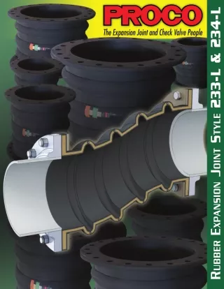
Proco Style 233-L & 234-L Rubber Joints Proco Style 233-L Rubber Expansion Joints are designed for piping systems that experience large lateral offsets due to settlement. The Style 233-L is a low profile triple arch design with a built-in reinforcing ring at the top of the arch to provide extra stability for lateral movements up to 4”. Proco Style FA233-L Rubber Expansion Joints are designed for piping systems carrying heavy solids that experience large lateral offsets due to settlement. The Style FA233-L is a low profile triple filled arch design with a built-in reinforcing ring at the top of the arch to provide extra stability for lateral movements up to 2”. Proco Style 234-L Rubber Expansion Joints are designed for piping systems that experience large lateral offsets due to settlement. The Style 234-L is a low profile quadruple arch design with a built-in reinforcing ring at the top of the arch to provide extra stability for lateral movements up to 8”. Proco Style FA234-L Rubber Expansion Joints are designed for piping systems carrying heavy solids that experience large lateral offsets due to settlement. The Style FA234-L is a low profile quadruple filled arch design with a built-in reinforcing ring at the top of the arch to provide extra stability for lateral movements up to 4”. Features and Benefits: Absorbs Directional Movement Thermal movements appear in any rigid pipe system due to temperature changes. The Style 233-L and 234-L low profile arch allows for axial compression or axial extension, lateral deflection as well as angular and torsional movements. (Note: Rated movements in this publication are based on one plane movements. Multiple movement conditions are based on a multiple movement calculation. Contact Proco for information when designing multiple pipe movements.) Absorbs Vibration, Noise and Shock The Style 233-L and 234-L expansion joints are manufactured with the integral rubber flange joining the body at a true 90º angle. This ensures the product will install snug against the mating pipe flange free of voids creating less turbulence in the pipe system. Compensates for Misalignment The Style 233-L and 234-L expansion joints are designed for large lateral movements due to long term settlement. (Although rubber expansion joints can be made with permanent offsets, it is suggested that piping misalignments be limited to no more than 1/8” per the Fluid Sealing Association Piping Expansion Technical Handbook www.fluidsealing.com.) Wide Service Range and Less Weight Engineered to operate up to 145 PSIG (nominal size dependent) or up to 250ºF (elastomer dependent), the Series 233-L and 234-L can be specified for a wide range of piping system requirements. The Series 233-L and 234-L rubber expansion joints are constructed in various elastomers with rubber impregnated polyester tire cord and a reinforcing ring at the top of the arch to provide stability in large lateral offset conditions. Material Identification All 233-L and 234-L expansion joints are strip branded with cure dates and elastomer designations. Table 1: Available Materials • Temperatures For Specific Chemical Compatibilities, See: PROCO “Chemical To Elastomer Guide” EE-NSF/61 - ANSI/NSF Standard 61 standards were developed by the National Sanitation Foundation (NSF), and the American National Standards Institute (ANSI) and relates to water treatment which establishes stringent requirements for the control of equipment that comes in contact with either potable water or products that support the production of potable water Large Inventory Proco Products, Inc. maintains one of the largest inventories of rubber expansion joints in the world. Please contact us for price and availability. Maximum Operating Temp. ºF (ºC) 250º (121º) 250º (121º) 250º (121º) 250º (121º) 212º (100º) 225º (107º) 225º (107º) 212º (100º) 180º (82º) Branding Label Color Black Red Red Red2 Green Blue Blue2 Yellow White F.S.A. Material Class STD. III STD. III STD. III STD. II STD. II STD. II STD. II STD. II STD. I Cover 1,2 Elastomer Tube Elastomer Materal Code Chlorobutyl EPDM EPDM EPDM Neoprene Neoprene Neoprene Neoprene Neoprene Chlorobutyl EPDM EPDM FDA-EPDM CSM Neoprene FDA-Neoprene Nitrile Natural Rubber BB EE EE-NSF/614 EQ NH NN NF NP NR Protecting Piping and Equipment Systems from Stress/Motion Information subject to change without notice. Notes: All Products are reinforced with Polyester Tire Cord 1. Expansion Joint “Cover” can be coated with CSM UV Resistant Coating. 2. Branding Label will be marked as “Food Grade”. 3. All elastomers above are not intended for steam service. 4. EE-NSF/61 UL Classified Water Quality File MH47689 1
Style 233-L Style FA233-L Style 234-L Style FA234-L sales@procoproducts.com • (800) 344-3246 2
Style 233-L Performance Data Table 2: Sizes • Movements • Design Pressures • Weights 233-L Movement Capability: 1 From Neutral Position (Non-Concurrent) Weights Ibs / (kgs) 3 Operating Conditions 2 Expansion Joint Size Nom. I.D. Inch / (mm) Neutral Length Inch / (mm) Angular Deflection 4 Hg / (mm of Hg) 7 Torsional Rotation 5 Positive PSIG (Bar) Vacuum Inches of Axial Compression Lateral Deflection Expansion Joint Axial Extension Thrust Factor 6 Inch / (mm) Inch / (mm) Inch / (mm) In2 / (cm2) Retaining (Degrees) (Degrees) Ring Set 4 14 2.36 (60) 2.36 (60) 2.36 (60) 2.36 (60) 2.36 (60) 2.36 (60) 2.36 (60) 2.36 (60) 2.36 (60) 2.75 (70) 2.75 (70) 2.75 (70) 2.75 (70) 2.75 (70) 2.75 (70) 1.57 (40) 1.57 (40) 1.57 (40) 1.57 (40) 1.57 (40) 1.57 (40) 1.57 (40) 1.57 (40) 1.57 (40) 1.97 (50) 1.97 (50) 1.97 (50) 1.97 (50) 1.97 (50) 1.97 (50) 10.03 (64) 13.04 (84) 16.44 (106) 24.41 (157) 33.95 (219) 45.06 (290) 72.00 (469) 105.22 (678) 153.25 (988) 200.27 (1292) 253.58 (1636) 313.17 (2020) 379.05 (2445) 562.25 (3627) 742.93 (4793) 145 (10) 145 (10) 145 (10) 145 (10) 145 (10) 145 (10) 145 (10) 145 (10) 145 (10) 145 (10) 145 (10) 145 (10) 145 (10) 109 (7.5) 109 (7.5) 26 5.0 (2.3) 6.0 (2.8) 9.0 (4.1) 12.0 (5.3) 14.0 (6.5) 26.0 (11.6) 34.0 (15.2) 42.0 (19.6) 56.0 (25.4) 69.0 (31.2) 82.0 (37.1) 90.0 (40.8) 127.0 (52.9) 150.0 (67.7) 217.0 (98.3) 4.0 (1.8) 4.5 (2.0) 5.5 (2.5) 8.0 (3.6) 8.5 (3.9) 9.5 (4.3) 14.5 (6.6) 17.0 (7.7) 24.5 (33.5) 27.0 (12.2) 33.5 (15.2) 34.0 (15.4) 38.0 (17.2) 48.0 (21.8) 55.0 (24.9) 2 57.6º 2º (50) 2.5 (65) 3 (80) 4 (100) 5 (125) 6 (150) 8 (200) 10 (250) 12 (300) 14 (350) 16 (400) 18 (450) 20 (500) 24 (600) 28 (700) (356) 14 (356) 14 (356) 14 (356) 14 (356) 20 (508) 20 (508) 20 (508) 22 (559) 22 (559) 22 (559) 22 (559) 22 (559) 22 (559) 26 (660) (660) 26 (660) 26 (660) 26 (660) 26 (660) 26 (660) 26 (660) 26 (660) 26 (660) 26 (660) 26 (660) 26 (660) 26 (660) 26 (660) 26 (660) (100) 4 (100) 4 (100) 4 (100) 4 (100) 4 (100) 4 (100) 4 (100) 4 (100) 4 (100) 4 (100) 4 (100) 4 (100) 4 (100) 4 (100) 51.6º 2º 46.4º 2º 38.2º 2º 32.2º 2º 27.7º 2º 21.5º 2º 17.5º 2º 14.7º 2º 15.7º 2º 13.8º 2º 12.3º 2º 11.1º 2º 9.3º 2º 8.0º 2º See Notes Page 4 3
Table 2: Sizes • Movements • Design Pressures • Weights 233-L Movement Capability: 1 From Neutral Position (Non-Concurrent) Weights Ibs / (kgs) 3 Operating Conditions 2 Expansion Joint Size Nom. I.D. Inch / (mm) Neutral Length Inch / (mm) Hg / (mm of Hg) 7 Torsional Rotation 5 Lateral Deflection 4 Positive PSIG (Bar) Angular Deflection Vacuum Inches of Axial Compression Expansion Joint Axial Extension Thrust Factor 6 Inch / (mm) Inch / (mm) Inch / (mm) In2 / (cm2) Retaining (Degrees) (Degrees) Ring Set 4 842.69 (5436) 1179.68 (7610) 1573.22 (10149) 2023.31 (13053) 2460.24 (15872) 3016.00 (19458) 26 2.75 (70) 2.75 (70) 2.75 (70) 2.75 (70) 2.75 (70) 2.75 (70) 1.97 (50) 1.97 (50) 1.97 (50) 1.97 (50) 1.97 (50) 1.97 (50) 73 (5) 73 (5) 73 (5) 73 (5) 73 (5) 73 (5) 26 232.0 (105.4) 287.0 (130.0) 369.0 (179.8) 428.0 (193.9) 548.0 (248.5) 667.0 (302.7) 63.0 (28.6) 76.0 (34.5) 100.0 (45.4) 132.0 (59.9) 150.0 (68.0) 200.0 (90.7) 30 (750) 36 (900) 42 (1050) 48 (1200) 54 (1350) 60 (1500) 7.5º 2º (660) 26 (660) 28 (711) 28 (711) 28 (711) 30 (762) (660) 26 (660) 26 (660) 26 (660) 26 (660) 26 (660) (100) 4 (100) 4 (100) 4 (100) 4 (100) 4 (100) 6.2º 2º 5.4º 2º 4.7º 2º 4.2º 2º 3.8º 2º NOTES: 1. Concurrent Movements - Concurrent movements are developed when two or more movements in a pipe system occur at the same time. If multiple movements exceed single arch design there may be a need for additional arches. To perform calculation for concurrent movement when a pipe system design has more than one movement, please use the following formula: Actual Axial Compression + Actual Axial Extension + Actual Lateral (X) + Actual Lateral (Y) = / <1 Rated Axial Compression + Rated Axial Extension + Rated Lateral (X) + Rated Lateral (Y) Calculation must be equal to or less than 1 for expansion joint to operate within concurrent movement capability. 2. Pressure rating is based on 170˚ F operating temperature with a 4:1 safety factor. At higher temperatures, the pressure rating is reduced slightly. Hydrostatic testing at 1.5 times rated maximum catalog pressure or design working pressure of pipe system for 10 minutes is available upon request. 3. Weights are approximate. 4. The degree of angular movement is based on the maximum rated extension. 5. Torsional movement is expressed when the expansion joint is at neutral length. 6. Calculation of Thrust: When expansion joints are installed in the pipeline, the static portion of the thrust is calculated as a product of the area of the I.D. of the arch of the expansion joint times the maximum pressure (design, test or surge) that will occur in the line. The result is a force expressed in pounds. Take design, surge or test pressure times the thrust factor to calculate end thrust. For filled arch configurations use the cross-sectional area of the pipe, π-4(Pipe I.D.)2’, multiplied by the pressure to calculate the end thrust. “Calculation of Thrust” T = Thrust Tf = Thrust Factor P = Presure (Design, Test or Surge) T = (Tf) (P) 7. Parts listed at 26” Hg / 660 mm Hg vacuum have a design rating of 30” Hg / 762 mm Hg (full vacuum). Vacuum rating is based on neutral installed length, without external load. Products should not be installed “extended” on vacuum applications. sales@procoproducts.com • (800) 344-3246 4
Style FA233-L Performance Data Table 3: Sizes • Movements • Design Pressures • Weights FA233-L Movement Capability: 1 From Neutral Position (Non-Concurrent) Weights Ibs / (kgs) 3 Operating Conditions 2 Expansion Joint Size Nom. I.D. Inch / (mm) Neutral Length Inch / (mm) Angular Deflection 4 Hg / (mm of Hg) 7 Torsional Rotation 5 Positive PSIG (Bar) Vacuum Inches of Axial Compression Lateral Deflection Expansion Joint Axial Extension Thrust Factor 6 Inch / (mm) Inch / (mm) Inch / (mm) In2 / (cm2) Retaining (Degrees) (Degrees) Ring Set 2 3.14 (20) 4.91 (31) 7.07 (45) 12.57 (81) 19.64 (126) 28.27 (182) 50.27 (324) 78.54 (506) 113.10 (729) 153.94 (993) 201.06 (1297) 254.47 (1641) 314.16 (2026) 452.39 (2918) 615.75 (3972) 4.0 (1.8) 4.5 (2.0) 5.5 (2.5) 8.0 (3.6) 8.5 (3.9) 9.5 (4.3) 14.5 (6.6) 17.0 (7.7) 24.5 (11.1) 27.0 (12.2) 33.5 (15.4) 34.0 (15.4) 38.0 (17.2) 48.0 (21.8) 55.0 (24.9) 14 1.18 (30) 1.18 (30) 1.18 (30) 1.18 (30) 1.18 (30) 1.18 (30) 1.18 (30) 1.18 (30) 1.18 (30) 1.38 (35) 1.38 (35) 1.38 (35) 1.38 (35) 1.38 (35) 1.38 (35) .78 (20) .78 (20) .78 (20) .78 (20) .78 (20) .78 (20) .78 (20) .78 (20) .78 (20) 1.0 (25) 1.0 (25) 1.0 (25) 1.0 (25) 1.0 (25) 1.0 (25) 145 (10) 145 (10) 145 (10) 145 (10) 145 (10) 145 (10) 145 (10) 145 (10) 145 (10) 145 (10) 145 (10) 145 (10) 145 (10) 109 (7.5) 109 (7.5) 26 6.0 (2.9) 8.0 (3.5) 11.0 (5.1) 15.0 (6.6) 18.0 (8.1) 33.0 (14.5) 43.0 (19.0) 53.0 (24.5) 70.0 (31.8) 86.0 (39.0) 103.0 (46.4) 113.0 (51.0) 159.0 (65.9) 188.0 (84.6) 271.0 (122.9) 2 28.8º 1º (50) 2.5 (65) 3 (80) 4 (100) 5 (125) 6 (150) 8 (200) 10 (250) 12 (300) 14 (350) 16 (400) 18 (450) 20 (500) 24 (600) 28 (700) (356) 14 (356) 14 (356) 14 (356) 14 (356) 20 (508) 20 (508) 20 (508) 22 (559) 22 (559) 22 (559) 22 (559) 22 (559) 22 (559) 26 (660) (660) 26 (660) 26 (660) 26 (660) 26 (660) 26 (660) 26 (660) 26 (660) 26 (660) 26 (660) 26 (660) 26 (660) 26 (660) 26 (660) 26 (660) (50) 2 (50) 2 (50) 2 (50) 2 (50) 2 (50) 2 (50) 2 (50) 2 (50) 2 (50) 2 (50) 2 (50) 2 (50) 2 (50) 2 (50) 25.8º 1º 23.2º 1º 19.1º 1º 16.1º 1º 13.8º 1º 10.8º 1º 8.8º 1º 7.3º 1º 7.8º 1º 6.9º 1º 6.1º 1º 5.6º 1º 4.6º 1º 4.0º 1º See Notes Page 4 5
Table 3: Sizes • Movements • Design Pressures • Weights FA233-L Movement Capability: 1 From Neutral Position (Non-Concurrent) Weights Ibs / (kgs) 3 Operating Conditions 2 Expansion Joint Size Nom. I.D. Inch / (mm) Neutral Length Inch / (mm) Angular Deflection 4 Hg / (mm of Hg) 7 Torsional Rotation 5 Positive PSIG (Bar) Vacuum Inches of Axial Compression Lateral Deflection Expansion Joint Axial Extension Thrust Factor 6 Inch / (mm) Inch / (mm) Inch / (mm) In2 / (cm2) Retaining (Degrees) (Degrees) Ring Set 2 26 1.38 (35) 1.38 (35) 1.38 (35) 1.38 (35) 1.38 (35) 1.38 (35) 1.0 (25) 1.0 (25) 1.0 (25) 1.0 (25) 1.0 (25) 1.0 (25) 706.86 (4560) 1017.88 (6566) 1385.44 (8938) 1809.56 (11674) 2290.22 (14775) 2827.43 (18241) 73 (5) 73 (5) 73 (5) 73 (5) 73 (5) 73 (5) 26 290.0 (131.8) 359.0 (162.5) 495.0 (224.8) 535.0 (242.4) 685.0 (310.6) 833.0 (378.4) 63.0 (28.6) 76.0 (34.5) 100.0 (45.4) 132.0 (59.9) 150.0 (68.0) 200.0 (90.7) 30 (750) 36 (900) 42 (1050) 48 (1200) 54 (1350) 60 (1500) 3.8º 1º (660) 26 (660) 28 (711) 28 (711) 28 (711) 30 (762) (660) 26 (660) 26 (660) 26 (660) 26 (660) 26 (660) (50) 2 (50) 2 (50) 2 (50) 2 (50) 2 (50) 3.1º 1º 2.7º 1º 2.4º 1º 2.1º 1º 1.9º 1º NOTES: 1. Concurrent Movements - Concurrent movements are developed when two or more movements in a pipe system occur at the same time. If multiple movements exceed single arch design there may be a need for additional arches. To perform calculation for concurrent movement when a pipe system design has more than one movement, please use the following formula: Actual Axial Compression + Actual Axial Extension + Actual Lateral (X) + Actual Lateral (Y) = / <1 Rated Axial Compression + Rated Axial Extension + Rated Lateral (X) + Rated Lateral (Y) Calculation must be equal to or less than 1 for expansion joint to operate within concurrent movement capability. 2. Pressure rating is based on 170˚ F operating temperature with a 4:1 safety factor. At higher temperatures, the pressure rating is reduced slightly. Hydrostatic testing at 1.5 times rated maximum catalog pressure or design working pressure of pipe system for 10 minutes is available upon request. 3. Weights are approximate. 4. The degree of angular movement is based on the maximum rated extension. 5. Torsional movement is expressed when the expansion joint is at neutral length. 6. Calculation of Thrust: When expansion joints are installed in the pipeline, the static portion of the thrust is calculated as a product of the area of the I.D. of the arch of the expansion joint times the maximum pressure (design, test or surge) that will occur in the line. The result is a force expressed in pounds. Take design, surge or test pressure times the thrust factor to calculate end thrust. For filled arch configurations use the cross-sectional area of the pipe, π-4(Pipe I.D.)2’, multiplied by the pressure to calculate the end thrust. “Calculation of Thrust” T = Thrust Tf = Thrust Factor P = Presure (Design, Test or Surge) T = (Tf) (P) 7. Parts listed at 26” Hg / 660 mm Hg vacuum have a design rating of 30” Hg / 762 mm Hg (full vacuum). Vacuum rating is based on neutral installed length, without external load. Products should not be installed “extended” on vacuum applications. sales@procoproducts.com • (800) 344-3246 6
Style 234-L Performance Data Table 4: Sizes • Movements • Design Pressures • Weights 234-L Movement Capability: 1 From Neutral Position (Non-Concurrent) Weights Ibs / (kgs) 3 Operating Conditions 2 Expansion Joint Size Nom. I.D. Inch / (mm) Neutral Length Inch / (mm) Angular Deflection 4 Hg / (mm of Hg) 7 Torsional Rotation 5 Positive PSIG (Bar) Vacuum Inches of Axial Compression Lateral Deflection Expansion Joint Axial Extension Thrust Factor 6 Inch / (mm) Inch / (mm) Inch / (mm) In2 / (cm2) Retaining (Degrees) (Degrees) Ring Set 8 18 2.75 (70) 2.75 (70) 2.75 (70) 2.75 (70) 2.75 (70) 2.75 (70) 2.75 (70) 2.75 (70) 2.75 (70) 3.15 (80) 3.15 (80) 3.15 (80) 3.15 (80) 3.15 (80) 3.15 (80) 1.97 (50) 1.97 (50) 1.97 (50) 1.97 (50) 1.97 (50) 1.97 (50) 1.97 (50) 1.97 (50) 1.97 (50) 2.36 (60) 2.36 (60) 2.36 (60) 2.36 (60) 2.36 (60) 2.36 (60) 10.03 (64) 13.04 (84) 16.44 (106) 24.41 (157) 33.95 (219) 45.06 (290) 72.00 (469) 105.22 (678) 153.25 (988) 200.27 (1292) 253.58 (1636) 313.17 (2020) 379.05 (2445) 562.25 (3627) 742.93 (4793) 145 (10) 145 (10) 145 (10) 145 (10) 145 (10) 145 (10) 145 (10) 145 (10) 145 (10) 145 (10) 145 (10) 145 (10) 145 (10) 109 (7.5) 109 (7.5) 26 6.0 (2.8) 7.0 (3.4) 11.0 (5.1) 15.0 (6.6) 18.0 (8.1) 31.0 (14.1) 41.0 (18.4) 50.0 (22.6) 66.0 (30.0) 82.0 (37.3) 97.0 (44.1) 107.0 (48.7) 141.0 (63.8) 180.0 (81.4) 260.0 (117.9) 4.0 (1.8) 4.5 (2.0) 5.5 (2.5) 8.0 (3.6) 8.5 (3.9) 9.5 (4.3) 14.5 (6.6) 17.0 (7.7) 24.5 (33.5) 27.0 (12.2) 33.5 (15.2) 34.0 (15.4) 38.0 (17.2) 48.0 (21.8) 55.0 (24.9) 2 63.1º 2º (50) 2.5 (65) 3 (80) 4 (100) 5 (125) 6 (150) 8 (200) 10 (250) 12 (300) 14 (350) 16 (400) 18 (450) 20 (500) 24 (600) 28 (700) (457) 18 (457) 18 (457) 18 (457) 18 (457) 24 (610) 24 (610) 24 (610) 26 (660) 26 (660) 26 (660) 26 (660) 26 (660) 26 (660) 30 (762) (660) 26 (660) 26 (660) 26 (660) 26 (660) 26 (660) 26 (660) 26 (660) 26 (660) 26 (660) 26 (660) 26 (660) 26 (660) 26 (660) 26 (660) (200) 8 (200) 8 (200) 8 (200) 8 (200) 8 (200) 8 (200) 8 (200) 8 (200) 8 (200) 8 (200) 8 (200) 8 (200) 8 (200) 8 (200) 57.6º 2º 52.7º 2º 44.5º 2º 38.2º 2º 33.3º 2º 26.2º 2º 21.5º 2º 18.2º 2º 18.6º 2º 16.5º 2º 14.7º 2º 13.3º 2º 11.1º 2º 9.6º 2º See Notes Page 4 7
Table 4: Sizes • Movements • Design Pressures • Weights 234-L Movement Capability: 1 From Neutral Position (Non-Concurrent) Weights Ibs / (kgs) 3 Operating Conditions 2 Expansion Joint Size Nom. I.D. Inch / (mm) Neutral Length Inch / (mm) Angular Deflection 4 Hg / (mm of Hg) 7 Torsional Rotation 5 Positive PSIG (Bar) Vacuum Inches of Axial Compression Lateral Deflection Expansion Joint Axial Extension Thrust Factor 6 Inch / (mm) Inch / (mm) Inch / (mm) In2 / (cm2) Retaining (Degrees) (Degrees) Ring Set 8 842.69 (5436) 1179.68 (7610) 1573.22 (10149) 2023.31 (13053) 2460.24 (15872) 3016.00 (19458) 30 3.15 (80) 3.15 (80) 3.15 (80) 3.15 (80) 3.15 (80) 3.15 (80) 2.36 (60) 2.36 (60) 2.36 (60) 2.36 (60) 2.36 (60) 2.36 (60) 73 (5) 73 (5) 73 (5) 73 (5) 73 (5) 73 (5) 26 278.0 (126.3) 341.0 (154.6) 468.0 (212.3) 567.0 (257.3) 646.0 (293.2) 834.0 (378.5) 63.0 (28.6) 76.0 (34.5) 100.0 (45.4) 132.0 (59.9) 150.0 (68.0) 200.0 (90.7) 30 (750) 36 (900) 42 (1050) 48 (1200) 54 (1350) 60 (1500) 8.9º 2º (762) 30 (762) 32 (813) 32 (813) 32 (813) 38 (965) (660) 26 (660) 26 (660) 26 (660) 26 (660) 26 (660) (200) 8 (200) 8 (200) 8 (200) 8 (200) 8 (200) 7.5º 2º 6.4º 2º 5.6º 2º 5.0º 2º 4.5º 2º NOTES: 1. Concurrent Movements - Concurrent movements are developed when two or more movements in a pipe system occur at the same time. If multiple movements exceed single arch design there may be a need for additional arches. To perform calculation for concurrent movement when a pipe system design has more than one movement, please use the following formula: Actual Axial Compression + Actual Axial Extension + Actual Lateral (X) + Actual Lateral (Y) = / <1 Rated Axial Compression + Rated Axial Extension + Rated Lateral (X) + Rated Lateral (Y) Calculation must be equal to or less than 1 for expansion joint to operate within concurrent movement capability. 2. Pressure rating is based on 170˚ F operating temperature with a 4:1 safety factor. At higher temperatures, the pressure rating is reduced slightly. Hydrostatic testing at 1.5 times rated maximum catalog pressure or design working pressure of pipe system for 10 minutes is available upon request. 3. Weights are approximate. 4. The degree of angular movement is based on the maximum rated extension. 5. Torsional movement is expressed when the expansion joint is at neutral length. 6. Calculation of Thrust: When expansion joints are installed in the pipeline, the static portion of the thrust is calculated as a product of the area of the I.D. of the arch of the expansion joint times the maximum pressure (design, test or surge) that will occur in the line. The result is a force expressed in pounds. Take design, surge or test pressure times the thrust factor to calculate end thrust. For filled arch configurations use the cross-sectional area of the pipe, π-4(Pipe I.D.)2’, multiplied by the pressure to calculate the end thrust. “Calculation of Thrust” T = Thrust Tf = Thrust Factor P = Presure (Design, Test or Surge) T = (Tf) (P) 7. Parts listed at 26” Hg / 660 mm Hg vacuum have a design rating of 30” Hg / 762 mm Hg (full vacuum). Vacuum rating is based on neutral installed length, without external load. Products should not be installed “extended” on vacuum applications. sales@procoproducts.com • (800) 344-3246 8
Style FA234-L Performance Data Table 5: Sizes • Movements • Design Pressures • Spring Rates Movement Operating Conditions Spring Rates Expansion Joint Size Nom. I.D. Inch / (mm) Neutral Length Inch / (mm) Maxium Pressure Rating Maxium Vacuum Rating In. Hg / (mm of Hg) Angular Deflection 4 Torsional Rotation 5 lbs/in. / (N/mm) lbs/in. / (N/mm) lbs/in. / (N/mm) Angular Deflection ft-lbs/º / (Nm/º) Axial Compression Axial Compression Lateral Deflection Lateral Deflection Axial Extemsion Axial Extension Thrust Factor 6 Inch / (mm) Inch / (mm) Inch / (mm) PSIG /(Bar) In2 / (cm2) (Degrees) (Degrees) 4 3.14 (20) 4.91 (32) 7.07 (46) 12.57 (81) 19.64 (127) 28.27 (182) 50.27 (324) 78.54 (507) 113.1 (730) 153.94 (993) 201.06 (1297) 254.47 (1642) 314.16 (2027) 452.39 (2919) 615.75 (3973) 699 (121) 875 (152) 1050 (183) 1402 (245) 1749 (306) 2101 (386) 2335 (408) 2919 (512) 3502 (613) 3065 (536) 3502 (613) 3938 (690) 4381 (767) 5255 (919) 5451 (955) 913 (159) 1140 (198) 1369 (240) 1826 (320) 2276 (399) 2732 (478) 3038 (531) 3797 (666) 4556 (798) 3987 (699) 4556 (798) 5129 (897) 5689 (997) 6829 (1195) 7087 (1241) 1158 (203) 1259 (221) 1363 (238) 1574 (276) 1806 (315) 2040 (357) 2489 (437) 2675 (467) 3136 (549) 3693 (646) 4253 (745) 4697 (822) 5252 (919) 5643 (988) 6456 (1131) 0.49 (0.66) 0.83 (1.12) 1.32 (1.79) 3.14 (4.26) 7 (9) 11 (15) 22 (29) 40 (53) 71 (95) 31 (42) 126 (170) 176 (238) 251 (342) 452 (613) 631 (856) 18 1.38 (35) 1.38 (35) 1.38 (35) 1.38 (35) 1.38 (35) 1.38 (35) 1.38 (35) 1.38 (35) 1.38 (35) 1.57 (40) 1.57 (40) 1.57 (40) 1.57 (40) 1.57 (40) 1.57 (40) 1 145 (10) 145 (10) 145 (10) 145 (10) 145 (10) 145 (10) 145 (10) 145 (10) 145 (10) 145 (10) 145 (10) 145 (10) 145 (10) 109 (7.5) 109 (7.5) 26 2 31.5º 1º (50) 2.5 (65) 3 (75) 4 (100) 5 (125) 6 (150) 8 (200) 10 (250) 12 (300) 14 (350) 16 (400) 18 (450) 20 (500) 24 (600) 28 (700) (457) 18 (457) 18 (457) 18 (457) 18 (457) 24 (610) 24 (610) 24 (610) 26 (660) 26 (660) 26 (660) 26 (660) 26 (660) 26 (660) 30 (762) (25) 1 (25) 1 (25) 1 (25) 1 (25) 1 (25) 1 (25) 1 (25) 1 (25) 1.18 (30) 1.18 (30) 1.18 (30) 1.18 (30) 1.18 (30) 1.18 (30) (660) 26 (660) 26 (660) 26 (660) 26 (660) 26 (660) 26 (660) 26 (660) 26 (660) 26 (660) 26 (660) 26 (660) 26 (660) 26 (660) 26 (660) (100) 4 (100) 4 (100) 4 (100) 4 (100) 4 (100) 4 (100) 4 (100) 4 (100) 4 (100) 4 (100) 4 (100) 4 (100) 4 (100) 4 (100) 28.8º 1º 26.3º 1º 22.2º 1º 19.1º 1º 16.6º 1º 13.1º 1º 10.7º 1º 9.1º 1º 9.3º 1º 8.2º 1º 7.3º 1º 6.6º 1º 5.5º 1º 4.8º 1º See Notes Page 4 9
Table 5: Sizes • Movements • Design Pressures • Spring Rates Movement Operating Conditions Spring Rates Expansion Joint Size Nom. I.D. Inch / (mm) Neutral Length Inch / (mm) Angular Deflection 4 Hg / (mm of Hg) 7 Torsional Rotation 5 Positive PSIG (Bar) lbs/in. / (N/mm) lbs/in. / (N/mm) lbs/in. / (N/mm) Angular Deflection Vacuum Inches of ft-lbs/º / (Nm/º) Axial Compression Axial Compression Lateral Deflection Lateral Deflection Axial Extemsion Axial Extension Thrust Factor 6 Inch / (mm) Inch / (mm) Inch / (mm) In2 / (cm2) (Degrees) (Degrees) 4 5841 (1023) 7007 (1226) 7362 (1290) 8412 (1473) 9466 (1658) 10518 (1841) 6862 (1202) 10465 (1832) 11320 (1982) 12787 (2240) 14231 (2492) 15664 (2743) 723 (981) 1396 (2042) 1923 (2606) 3019 (4092) 3817 (5175) 5850 (7931) 30 1.57 (40) 1.57 (40) 1.57 (40) 1.57 (40) 1.57 (40) 1.57 (40) 1.18 (30) 1.18 (30) 1.18 (30) 1.18 (30) 1.18 (30) 1.18 (30) 706.86 (4560) 1017.88 (6567) 1385.44 (8938) 1809.56 (11675) 2290.22 (14776) 2827.43 (18241) 73 (5) 73 (5) 73 (5) 73 (5) 73 (5) 73 (5) 26 7596 (1330) 9115 (1596) 9563 (1674) 10928 (1914) 12295 (2152) 13673 (2395) 30 (750) 36 (900) 42 (1050) 48 (1200) 54 (1350) 60 (1500) 4.4º 1º (762) 30 (762) 32 (813) 32 (813) 32 (813) 38 (965) (660) 26 (660) 26 (660) 26 (660) 26 (660) 26 (660) (100) 4 (100) 4 (100) 4 (100) 4 (100) 4 (100) 3.7º 1º 3.2º 1º 2.8º 1º 2.5º 1º 2.2º 1º NOTES: 1. Movements are Non-Concurrent Concurrent movements are developed when two or more movements in a pipe system occur at the same time. To perform calculations for concurrent movement when a pipe system design has more than one movement, please use the following formula: Actual Axial + Actual Lateral + Actual Lateral = <1 Rated Axial Rated Lateral Rated Lateral Calculation must be equal to or less than 1 for expansion joint to operate within concurrent movement capabilities. 2. Pressure rating is based on 170˚ F operating temperature with a 4:1 safety factor. At higher temperatures, the pressure rating is reduced slightly. Hydrostatic testing at 1.5 times rated maximum pressure or design working pressure of pipe system for 10 minutes is available upon request. 3. The degree of angular movement is based on the maximum rated extension. 4. Torsional movement is expressed when the expansion joint is at neutral length. 5. Calculation of Thrust: When expansion joints are installed in the pipeline, the static portion of the thrust is calculated as a product of the area of the I.D. of the arch of the expansion joint times the maximum pressure (design, test or surge) that will occur in the line. The result is a force expressed in pounds. Take design, surge or test pressure times the thrust factor to calculate end thrust. For filled arch configurations use the cross-sectional area of the pipe, π-4(Pipe I.D.)2’, multiplied by the pressure to calculate the end thrust. “Calculation of Thrust” T = Thrust Tf = Thrust Factor P = Presure (Design, Test or Surge) T = (Tf) (P) 6. Parts listed at 26” Hg / 660 mm Hg vacuum have a design rating of 30” Hg / 762 mm Hg (full vacuum). Vacuum rating is based on neutral installed length, without external load. Products should not be installed “extended” on vacuum applications. 7. Spring Rates: The forces required to move the expansion joints are based on zero pressure conditions and room temperature in the pipe line. sales@procoproducts.com • (800) 344-3246 10
Style 233-L & 234-L Drilling Chart Table 6 Standard Drilling for PROCO Rubber Expansion Joints Flange Dimensions1,2 Thickness of Materials for PROCO Rubber Expansion Joints Material Thicknessfor Bolt Length Requirements Nominal Pipe Size Expan- sion Joint I.D. Inch /(mm) Number Of Holes Adjacent Mating Retaining Rings Thickness Inch / (mm) Rubber Flange Thickness Inch / (mm) Flange Thickness Bolt Circle Inch / (mm) Size Of Holes Inch / (mm) Flange O.D. Inch / (mm) 6.00 4.75 4 0.750 0.375 0.472 (50) (152.40) (120.65) (19.05) (9.53) (11.99) 2 C U S T O M E R 7.00 5.50 4 0.750 0.375 0.472 (65) (177.80) (139.70) (19.05) (9.53) (11.99) 2.5 3 4 5 6 8 10 12 14 16 18 20 22 24 26 28 30 36 42 48 54 7.50 6.00 4 0.750 0.375 0.472 (80) (190.50) (152.40) (19.05) (9.53) (11.99) 9.00 7.50 8 0.750 0.375 0.472 (100) (228.60) (190.50) (19.05) (9.53) (11.99) 10.00 8.50 8 0.875 0.375 0.551 (125) (254.00) (215.90) (22.23) (9.53) (14.00) 11.00 9.50 8 0.875 0.375 0.551 (150) (279.40) (241.30) (22.23) (9.53) (14.00) T O S P E C I F Y 13.50 11.75 8 0.875 0.375 0.630 (200) (342.90) (298.45) (22.23) (9.53) (16.00) 16.00 14.25 12 1.000 0.375 0.630 (250) (406.40) (361.95) (25.40) (9.53) (16.00) 19.00 17.00 12 1.000 0.375 0.748 (300) (482.60) (431.80) (25.40) (9.53) (19.00) 21.00 18.75 12 1.125 0.375 0.866 (350) (533.40) (476.25) (28.58) (9.53) (22.00) 23.50 21.25 16 1.125 0.375 0.866 (400) (596.90) (539.75) (28.58) (9.53) (22.00) M A T I N G 25.00 22.75 16 1.250 0.375 0.866 (450) (635.00) (577.85) (31.75) (9.53) (22.00) 27.50 25.00 20 1.250 0.375 0.984 (500) (698.50) (635.00) (31.75) (9.53) (24.99) 29.50 27.25 20 1.375 0.375 0.984 (550) (749.30) (692.15) (34.93) (9.53) (24.99) 32.00 29.50 20 1.375 0.375 0.984 (600) (812.80) (749.30) (34.93) (9.53) (24.99) F L A N G E T H I C K N E S S 34.25 31.75 24 1.375 0.375 0.984 (650) (869.95) (806.32) (34.93) (9.53) (24.99) 36.50 34.00 28 1.375 0.375 0.984 (700) (927.10) (863.60) (34.93) (9.53) (24.99) 38.75 36.00 28 1.375 0.375 0.984 (750) (984.25) (914.40) (34.93) (9.53) (24.99) 46.00 42.75 32 1.625 0.375 0.984 (900) (1168.40) (1085.85) (41.28) (9.53) (24.99) (1050) 53.00 (1346.20) 49.50 36 1.625 0.375 1.181 (1257.30) (41.28) (9.53) (30.00) (1200) 59.50 56.00 44 1.625 0.375 1.181 (1511.30) (1422.40) (41.28) (9.53) (30.00) (1350) 66.25 (1682.75) 62.75 44 2.000 0.375 1.181 (1593.85) (50.80) (9.53) (30.00) (1500) 73.00 (1854.20) 69.25 52 2.000 0.375 1.181 (1758.95) (50.80) (9.53) (30.00) 60 Metric Conversion Formula: Nominal I.D.: in. x 25 = mm; Dimensions/Thickness’: in. x 25.4 = mm. Notes: 1. Flange Dimensions shown are in accordance with ANSI B16.1 and ANSI B16.5 Class 125/150, AWWA C-207-07, Tbl 2 and 3 - Class D, Table 4 - Class E. Hole size shown is 1/8” larger than AWWA Standard. 2. Additional flange drilling such as 300 LB., PN10, PN16 and other special drilling’s are available upon request. 11
Limit Rods Upon Request A - Retaining Ring Thickness. B - Rubber Flange Thickness. C - Adjacent Mating Flange Thickness (By Others). D - Control Unit Plate Thickness. E - Double Nut Thickness is determined by Control Rod Diameter. F - Control Rod Bolt Length is determined by A through E + OAL 1. G - Control Rod Plate O.D. H - Maximum Rod Diameter 233-L 234-L sales@procoproducts.com • (800) 344-3246 12
Installation Instructions for Non-Metallic Expansion Joints 1. Service Conditions: Make sure the expansion joint rating for temperature, pressure, vacuum and movements match the system requirements. Contact the manufacturer for advice if the system requirements exceed those of the expansion joint selected. Check to make sure the elastomer selected is chemically compatible with the process fluid or gas. 2. Alignment: Expansion joints are normally not designed to make up for piping misalignment errors. Piping should be lined up within 1/8”. Misalignment reduces the rated movements of the expansion joint and can induce severe stress and reduce service life. Pipe guides should be installed to keep the pipe aligned and to prevent undue displacement. 3. Anchoring: Solid anchoring is required wherever the pipeline changes direction and expansion joints should be located as close as possible to anchor points. If piping is not adequately anchored, control rods should be used. If anchors are not used, pressure thrust may cause excessive movement damaging the expansion joint. 4. Pipe Support: Piping must be supported by hangers or anchors so expansion joints do not carry any pipe weight. 5. Mating Flanges: Install the expansion joint against the mating pipe flanges and install bolts so that the bolt head and washer are against the retaining rings. If washers are not used, flange leakage can result – particularly at the split in the retaining rings. Flange-to-flange dimension of the expansion joint must match the breech opening. Make sure the mating flanges are clean and are flat faced type or no more than 1/16” raised face type. Never install expansion joints that utilize split retaining rings next to wafer type check or butterfly valves. Serious damage can result to a rubber joint of this type unless installed against full face flanges. 6. Bolting Torque: Table 7 shows the recommended torque ranges for non-metallic expansion joints with full-faced rubber flanges: Torque specifications are approximate. Tighten bolts in stages using cross-bolt tightening pattern. If the joint has integral fabric and rubber flanges, the bolts should be tight enough to make the rubber flange OD bulge between the retaining rings and the mating flange. After installation, the system should be pressurized and examined to confirm a proper seal. Torque bolts sufficiently to assure leak- free operation at hydrostatic test pressure. Note: Torque values are approximate due to mating flange surfaces, installation offsets, operating pressures and environmental conditions. Table 7 Size 1” THRU 2” 2.5” THRU 5” 6” THRU 12” 14” THRU 18” 20” THRU 24” 26” THRU 40” 42” THRU 60” Approximate Torque Values 20 - 40 ft/lbs 25 - 60 ft/lbs 35 - 140 ft/lbs 50 - 180 ft/lbs 60 - 200 ft/lbs 70 - 300 ft/lbs 80 - 300 ft/lbs 7. Storage: Ideal storage is in a warehouse with a relatively dry, cool location. Store flanges face down on a pallet or wooden platform. Do not store other heavy items on top of expansion joints. Ten year shelf life can be expected with ideal conditions. If storage must be outdoors, place on wooden platform and joints should not be in contact with the ground. Cover with a tarpaulin. 8. Large Joint Handling: Do not lift with ropes or bars through the bolt holes. If lifting through the bore, use padding or a saddle to distribute the weight. Make sure cables or forklift tines do not contact the rubber. Do not let expansion joints sit vertically on the edges of the flanges for any period of time. 9. Additional Tips: A. Do not insulate over a non-metallic expansion joint; however, if insulation is required, it should be made removable to permit easy access to the flanges. This facilitates periodic inspection of the tightness of the joint bolting. B. It is acceptable (but not necessary) to lubricate the expansion joint flanges with a thin film of graphite dispersed in glycerin or water to ease disassembly at a later time. C. Do not weld in the near vicinity of a non-metallic joint. D. If expansion joints are to be installed underground, or will be submerged in water, contact manufacturer for specific recommendations. E. If the expansion joint will be installed outdoors, make sure the cover material will withstand ozone, sunlight, etc. F. Check the tightness of lead-free flanges two or three weeks after installation and retighten if necessary. Warning: Expansion joints may operate in pipelines or equipment carrying fluids and/or gasses at elevated temperature and pressures and may transport hazardous materials. Precautions should be taken to protect personnel in the event of leakage or splash. Rubber joints should not be installed in areas where inspection is impossible. Make sure proper drainage is available in the event of leakage when operating personnel are not available. 13
Settlement Examples Tank Before Settlement Tank After Settlement Anchor sales@procoproducts.com • (800) 344-3246 14
ALSO AVAILABLE FROM Proco Products, Inc. Proco Products, Inc. can supply tied universal expansion joints or hinged universal expansion joints for large lateral movements. Hinged Assembly Tied Rod Assembly 2431 North Wigwam Dr. (95205) P.O. Box 590 • Stockton, CA 95201-0590 • USA NATIONWIDE AND CANADA REPRESENTED BY: Toll-Free Phone: (800) 344-3246 Facsimile: (209) 943-0242 INTERNATIONAL (209) 943-6088 email: sales@procoproducts.com website: http://www.procoproducts.com Revised 4/24