Download
1 / 20
200 likes | 593 Views
GPS and Human Space Flight. . Miniaturized Airborne GPS Receiver (MAGR-S) Modified DoD receiver to replace TACAN on-board the Space ShuttleDesigned to accept inertial aiding and capable of using PPS Single-string system (retaining three-string TACAN) installed on OV-103 Discovery and OV-104 Atlantis, three-string system installed on OV-105 Endeavour (TACAN removed)GPS taken to navigation for the first time on STS-115 / OV-104 Atlantis.

E N D
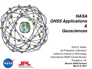
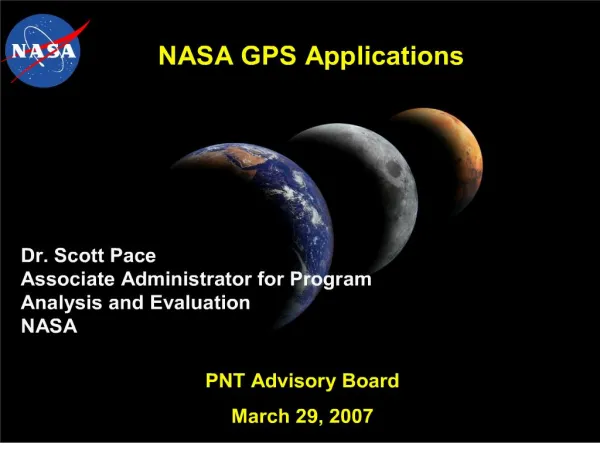
1. NASA GPS Applications
2. NASA�s Johnson Space Center is also involved in Research and Development efforts of GPS receivers for human spaceflight, such as the MAGR-S receiver being used on the Space Shuttle and the SIGI receiver currently on the International Space Station. Orbiters Discovery and Atlantis have a single, or single string, GPS receiver in addition to its three string TACAN while orbiter Endeavour has had its TACAN removed and replaced by a three-string GPS system. GPS was tracked during the re-entry of the last Space Shuttle mission, or STS-114 (shuttle Discovery), and is now certified for orbit and re-entry navigation.NASA�s Johnson Space Center is also involved in Research and Development efforts of GPS receivers for human spaceflight, such as the MAGR-S receiver being used on the Space Shuttle and the SIGI receiver currently on the International Space Station. Orbiters Discovery and Atlantis have a single, or single string, GPS receiver in addition to its three string TACAN while orbiter Endeavour has had its TACAN removed and replaced by a three-string GPS system. GPS was tracked during the re-entry of the last Space Shuttle mission, or STS-114 (shuttle Discovery), and is now certified for orbit and re-entry navigation.
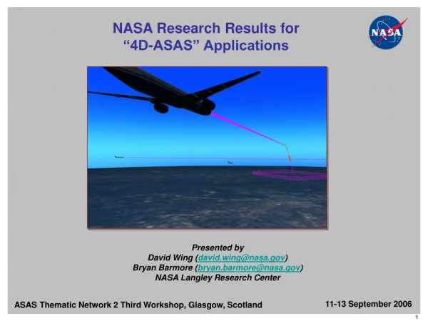
3. Navigation with GPS: Space-Based Range Space-based navigation, GPS, and Space Based Range Safety technologies are key components of the next generation launch and test range architecture
Provides a more cost-effective launch and range safety infrastructure while augmenting range flexibility, safety, and operability
Memorandum signed in November 2006 for GPS Metric Tracking (GPS MT) by January 1, 2011 for all DoD, NASA, and commercial vehicles launched at the Eastern and Western ranges
GPS is also a key component of the future Space-Based Range currently being developed by NASA with assistance from the DoD and the FAA. The space-based range involves relaying GPS position and time telemetry information during launches via NASA�s Tracking Data Relay Satellite system in Geostationary Earth Orbit, This provides a more cost-effective launch and range safety infrastructure while augmenting range flexibility, safety, and operability. GPS is also a key component of the future Space-Based Range currently being developed by NASA with assistance from the DoD and the FAA. The space-based range involves relaying GPS position and time telemetry information during launches via NASA�s Tracking Data Relay Satellite system in Geostationary Earth Orbit, This provides a more cost-effective launch and range safety infrastructure while augmenting range flexibility, safety, and operability.
4. Science Applications of GPS: Blackjack Science Receivers NASA is also involved in Research and Development of GPS receivers specialized for science applications in space, such as the Blackjack GPS receiver family. These have been in continuous development at the Jet Propulsion Laboratory since 1999 and are available in different configurations depending on the particular science applications they will be used for. These have already been used in a number of space missions, which are listed on this slide, and the results show centimeter-level accuracies. NASA is also involved in Research and Development of GPS receivers specialized for science applications in space, such as the Blackjack GPS receiver family. These have been in continuous development at the Jet Propulsion Laboratory since 1999 and are available in different configurations depending on the particular science applications they will be used for. These have already been used in a number of space missions, which are listed on this slide, and the results show centimeter-level accuracies.
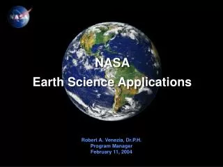
5. GPS is used in a number of science applications relating to monitoring the Earth.
->Press slide forward (text will appear under SOLID Earth)
It begins with monitoring the inner workings beneath Earth�s crust, such as monitoring Earths rotation and the motion of its axis, all the way to structure and evolution of its interior.
->Press slide forward (text will appear under OCEANS)
GPS is also used to monitor Earth�s oceans, such as significant variations in wave height (which is especially important after recent events such as the 2004 Tsunami in the Indian Ocean) all the way to the surface winds and their effect on the sea state.
->Press slide forward (text will appear under ATMOSPHERE and IONOSPHERE)
Finally, GPS is also used to monitor our Atmosphere, including the Ionosphere. This includes, among many other applications, monitoring the tropospheric water vapor distribution all the way Transient Ionospheric Disturbances and global energy transport through the Ionosphere.
GPS is used in a number of science applications relating to monitoring the Earth.
->Press slide forward (text will appear under SOLID Earth)
It begins with monitoring the inner workings beneath Earth�s crust, such as monitoring Earths rotation and the motion of its axis, all the way to structure and evolution of its interior.
->Press slide forward (text will appear under OCEANS)
GPS is also used to monitor Earth�s oceans, such as significant variations in wave height (which is especially important after recent events such as the 2004 Tsunami in the Indian Ocean) all the way to the surface winds and their effect on the sea state.
->Press slide forward (text will appear under ATMOSPHERE and IONOSPHERE)
Finally, GPS is also used to monitor our Atmosphere, including the Ionosphere. This includes, among many other applications, monitoring the tropospheric water vapor distribution all the way Transient Ionospheric Disturbances and global energy transport through the Ionosphere.
6. NASA and the Jet Propulsion Laboratory have developed the TDRSS Augmentation Satellites System, or TASS, to provide differential corrections to Earth-orbiting satellites via NASA�s Tracking and Data Relay Satellite System. This system operates as follows. A spacecraft determines its position using stand-alone GPS.
->Press slide forward (arrows appear showing the ground stations tracking the GPS satellites)
The GPS satellites are also tracked by JPL�s Global Differential GPS network of 70 reference stations equipped with dual-frequency receivers.
->Press slide forward (and arrow appears going from the surface to a TDRS satellite, and another from the TDRS satellites to the spacecraft)
The differential corrections are then relayed from the ground to the spacecraft via a TDRS satellites.
NASA and the Jet Propulsion Laboratory have developed the TDRSS Augmentation Satellites System, or TASS, to provide differential corrections to Earth-orbiting satellites via NASA�s Tracking and Data Relay Satellite System. This system operates as follows. A spacecraft determines its position using stand-alone GPS.
->Press slide forward (arrows appear showing the ground stations tracking the GPS satellites)
The GPS satellites are also tracked by JPL�s Global Differential GPS network of 70 reference stations equipped with dual-frequency receivers.
->Press slide forward (and arrow appears going from the surface to a TDRS satellite, and another from the TDRS satellites to the spacecraft)
The differential corrections are then relayed from the ground to the spacecraft via a TDRS satellites.
7. Search and Rescue with GPS:Distress Alerting Satellite System
8. Maintaining and Enhancing GPS: Satellite Laser Ranging
9. Navigation with GPS beyond LEO GPS Terrestrial Service Volume
Up to 3000 km altitude
Many current applications
GPS Space Service Volume (SSV)
3000 km altitude to GEO
Many emerging space users
Geostationary Satellites
High Earth Orbits (Apogee above GEO altitude)
SSV users share unique GPS signal challenges
Signal availability becomes more limited
GPS first side lobe signals are important
Robust GPS signals in the Space Service Volume needed
NASA GPS Navigator Receiver in development Although GPS is currently being successfully used in space, especially on the Space Shuttle and the International Space Station, there are significant challenges to using GPS in this environment, most obviously because GPS was not originally designed for this purpose.
Some of the challenges are due to the limited geometry between the satellite vehicle and space users, and the large signal changes due to variations in signal path lengths. Even with these problems, however, GPS is a practical utility for evolving space users, and the �market� for providing PNT services for such assets is growing. For this reason, NASA is now developing a GPS augmentation service for space users, which I will describe in a moment�
An example of some space users with requirements for meter-level orbit determination above 3000 km in what we call the space-service-volume are:
(1) Tracking and Data Relay Satellite System (TDRSS) and other GEO platforms for scientific measurements of the Earth & space weather, NOAA Operational Weather Satellites (GOES & NPOES series)
(2) US and International Space Weather satellites that monitor, for example, solar radiation levels which could affect the performance of other satellites
(3) US and International commercial telecommunications satellites (GEO)
(4) Supporting future Earth-Moon navigation efforts
Although GPS is currently being successfully used in space, especially on the Space Shuttle and the International Space Station, there are significant challenges to using GPS in this environment, most obviously because GPS was not originally designed for this purpose.
Some of the challenges are due to the limited geometry between the satellite vehicle and space users, and the large signal changes due to variations in signal path lengths. Even with these problems, however, GPS is a practical utility for evolving space users, and the �market� for providing PNT services for such assets is growing. For this reason, NASA is now developing a GPS augmentation service for space users, which I will describe in a moment�
An example of some space users with requirements for meter-level orbit determination above 3000 km in what we call the space-service-volume are:
(1) Tracking and Data Relay Satellite System (TDRSS) and other GEO platforms for scientific measurements of the Earth & space weather, NOAA Operational Weather Satellites (GOES & NPOES series)
(2) US and International Space Weather satellites that monitor, for example, solar radiation levels which could affect the performance of other satellites
(3) US and International commercial telecommunications satellites (GEO)
(4) Supporting future Earth-Moon navigation efforts
10. Navigation with GPS beyond Earth Orbit� and on to the Moon GPS signals effective up to the Earth-Moon 1st Lagrange Point (L1)
322,000 km from Earth
Approximately 4/5 the distance to the Moon
GPS signals can be tracked to the surface of the Moon, but not usable with current GPS receiver technology
11. Earth-Moon Communications and Navigation Architecture Options for Communications and/or Navigation:
Earth-based tracking, GPS, Lunar-orbiting communication and navigation satellites with GPS-like signals, Lunar surface beacons and/or Pseudolites
Objective: Integrated Interplanetary Communications, Time Dissemination, and Navigation
12. Architecture can accommodate evolutionary use of science orbiters as relays prior to deployment of any dedicated com/nav satellites at Mars
Surface beacons possible in areas of interest
Use of all available radiometric signals for positioning and navigation through integrated software defined radio (SDR)
SDR combines communications and navigation into a single device Earth-Mars Communication and Navigation Architecture
13. Planetary Time Transfer
14. GPS as a model for a Common Solar System Time
15. The Future of Positioning, Navigation, and Timing?
17. South Pole Outpost Lunar South Pole selected as location for outpost site
Elevated quantities of hydrogen, possibly water ice (e.g., Shackelton Crater)
Several areas with greater than 80% sunlight and less extreme temperatures
Incremental deployment of systems � one mission at a time
Power system
Communications/navigation
Habitat
Rovers
Etc. Why pick the South Pole to set up our outpost? There are a number of compelling reasons:
Clementine and Lunar Prospector data show that polar sites have elevated hydrogen levels. This is where we may find water. Even if we don�t find water, we can use the hydrogen and combine it with oxygen extracted separately to get water. The hydrogen deposits are located at the bottom of craters where the sun doesn�t shine due to the Moon�s orbit.
Sites at the top of mountains and crater rims near the poles experience a higher level of sunlight. Almost the entire Moon has about 14 days of daytime followed by 14 days of nighttime over the course of a lunar month. This equals 50% daylight during a month. Near the poles there are sites that experience 70-80% daylight. The amount of sunlight is a big driver for the power system. Solar arrays work in sunlight. During eclipses and nighttime, we have to use batteries that have stored energy during daytime. This leads to a big, heavy, costly power system unless we use nuclear power which has a different set of concerns. So long daylight allows us to use solar power.
We can break up our outpost site into a number of modules and bring them up piece by piece like the Space Station. A modular approach is flexible, allows future growth, and allows us to utilize modular contributions from others.Why pick the South Pole to set up our outpost? There are a number of compelling reasons:
Clementine and Lunar Prospector data show that polar sites have elevated hydrogen levels. This is where we may find water. Even if we don�t find water, we can use the hydrogen and combine it with oxygen extracted separately to get water. The hydrogen deposits are located at the bottom of craters where the sun doesn�t shine due to the Moon�s orbit.
Sites at the top of mountains and crater rims near the poles experience a higher level of sunlight. Almost the entire Moon has about 14 days of daytime followed by 14 days of nighttime over the course of a lunar month. This equals 50% daylight during a month. Near the poles there are sites that experience 70-80% daylight. The amount of sunlight is a big driver for the power system. Solar arrays work in sunlight. During eclipses and nighttime, we have to use batteries that have stored energy during daytime. This leads to a big, heavy, costly power system unless we use nuclear power which has a different set of concerns. So long daylight allows us to use solar power.
We can break up our outpost site into a number of modules and bring them up piece by piece like the Space Station. A modular approach is flexible, allows future growth, and allows us to utilize modular contributions from others.
18. Concept Outpost Build Up These two missions:
Deliver logistics in preparation for extended stays.
Begin conducting the 180 day Mars Analog test
Manifest 5a:
(4 crew, 30 days) Prepare for Mars Analog by deploying logistics to Outpost.
(4 crew, 180 days) Deploy the replacement rover and transfer supplies to the Outpost.These two missions:
Deliver logistics in preparation for extended stays.
Begin conducting the 180 day Mars Analog test
Manifest 5a:
(4 crew, 30 days) Prepare for Mars Analog by deploying logistics to Outpost.
(4 crew, 180 days) Deploy the replacement rover and transfer supplies to the Outpost.
19. Notional Shackleton Crater Rim Outpost Location with Activity Zones Shackleton Crater was selected as our test subject. It has the advantages of: high sunlight on the crater rim right next to potential volatile resources at the crater floor, benign thermal environment, and a large enough site for future growth (25 km diameter). The inset photo is a false color image of Shackleton Crater showing the average illumination. Note that it varies widely from completely black inside the crater where no sunlight reaches the surface to sites on the rim with more than 70% average sunlight. We selected one such site and used it as our first attempt at land use planning on another world. The drawing shows the crater rim (rounded arc near the top) and below that the rim with contour lines drawn based on illumination (not elevation!). Within the three contour zones, the innermost zone is where we find the area with 70+% illumination. This is as close as you can get to a tropical paradise island on the Moon. The orange �+� marks the actual South Pole, so our prime lunar real estate is in the opposite location of a tropical paradise on Earth. This region alone is about 5 km long and � km wide which seems like an area big enough for our first Moon town. The principle function that we want to place in this area is our solar arrays so that they can benefit from the maximum amount of available sunlight. Nearby we have placed the Habitation Zone � the sight of our first habitation modules. At the other end of this �sweet spot� there is a spot that would be ideal for solar astronomy where a telescope could make weeks of continuous observations of the sun and the resulting lunar environment. Near the Habitation Zone is the Landing Zone. About 40 precision landings could be performed in an area this size without worrying about hauling the landers out of the way. Next to this is a potential Resource Zone, a field that might offer a good place to scoop up regolith and truck it to a nearby processing plant. The little grid is actually 100 football fields in size. Volatile resources that can�t stand sunlight could be located a few kilometers away in the bottom of Shackleton Crater. Within that photo of the crater, a littler drawing is inset.Shackleton Crater was selected as our test subject. It has the advantages of: high sunlight on the crater rim right next to potential volatile resources at the crater floor, benign thermal environment, and a large enough site for future growth (25 km diameter). The inset photo is a false color image of Shackleton Crater showing the average illumination. Note that it varies widely from completely black inside the crater where no sunlight reaches the surface to sites on the rim with more than 70% average sunlight. We selected one such site and used it as our first attempt at land use planning on another world. The drawing shows the crater rim (rounded arc near the top) and below that the rim with contour lines drawn based on illumination (not elevation!). Within the three contour zones, the innermost zone is where we find the area with 70+% illumination. This is as close as you can get to a tropical paradise island on the Moon. The orange �+� marks the actual South Pole, so our prime lunar real estate is in the opposite location of a tropical paradise on Earth. This region alone is about 5 km long and � km wide which seems like an area big enough for our first Moon town. The principle function that we want to place in this area is our solar arrays so that they can benefit from the maximum amount of available sunlight. Nearby we have placed the Habitation Zone � the sight of our first habitation modules. At the other end of this �sweet spot� there is a spot that would be ideal for solar astronomy where a telescope could make weeks of continuous observations of the sun and the resulting lunar environment. Near the Habitation Zone is the Landing Zone. About 40 precision landings could be performed in an area this size without worrying about hauling the landers out of the way. Next to this is a potential Resource Zone, a field that might offer a good place to scoop up regolith and truck it to a nearby processing plant. The little grid is actually 100 football fields in size. Volatile resources that can�t stand sunlight could be located a few kilometers away in the bottom of Shackleton Crater. Within that photo of the crater, a littler drawing is inset.
20. Shackleton Crater Rim Size Comparison That is not a random rectangle, it�s a scaled map of downtown Washington, DC. In the middle of DC we have highlighted an area that is 5 km long and 3/5 km wide � the same size as that sweet spot with high illumination on the crater rim. That highlighted are is equivalent to the entire Washington Mall.That is not a random rectangle, it�s a scaled map of downtown Washington, DC. In the middle of DC we have highlighted an area that is 5 km long and 3/5 km wide � the same size as that sweet spot with high illumination on the crater rim. That highlighted are is equivalent to the entire Washington Mall.