Download
1 / 69
760 likes | 2.81k Views
Mobile satellite communication & vsat Supervised by: Dr. Hasan Abbas Presented by: E. Nagham Abbas WHY SATELLITE?

E N D
Supervised by: Dr. Hasan Abbas Presented by: E. Nagham Abbas
WHY SATELLITE? As internet traffic continues to grow at exponential rates world wide, internet services providers (ISP’S) everywhere are faced with the challenge of keeping up with demand for network bandwidth . Satellite-based internet connections are one of those solutions . Vsat has offered ISP’S and telecommunications service providers easily scalable.
1- faster installation: Satellite services are usually activated much more quickly than terrestrial fiber. An antenna , modem and satellite circuit can be provisioned in a few weeks. As a network grows, additional capacity can be obtained in just as short a time. KEY BENEFITS:
2-better network performance Satellite connections enhance network performance by linking directly to an internet backbone, bypassing congested Terrestrial lines and numerous router hops. In addition, dedicated Space segment, local loop circuits and ports into a major Internet backbone mean ISP’s do not share infrastructure, Another reason for slow or degraded connections over the traditional fiber line.
3-lower network costs: The broadcast nature of satellites allows for the simultaneous delivery of information to wide geographic areas without regard to terrestrial infrastructure or geographic barriers. This translates into a pricing structure that is distance insensitive, keeping costs down for international ISP’s, in addition, satellite capacity is easily matched to actual traffic patterns, meaning ISP’s pay only for what they need.
Network architecture the network architecture consists of the three entities: • user segment • ground segment • space segment.
Network Architecture (cont) • The User Segment: The user segment comprises of user terminal units: Terminals can be categorised into two main classes: • Mobile terminals :Mobile terminals can be divided into two categories: mobile personal terminals and mobile group terminals. Mobile personal terminals :often refer to hand-held and palm-top devices, on board a mobile platform, such as a car.
The User Segment (cont) Mobile group terminals: are designed for group usage and for installation on board a collective transport system such as a ship, cruise liner, train, bus or aircraft. • Portable terminals: lap-top computer.
The Ground Segment: The ground segment consists of three main network elements: • gateways, sometimes called fixed Earth stations (FES) • the network control centre (NCC) • the satellite control centre (SCC).
the ground segment • Gateways provide fixed entry points to the satellite access network by public switched telephone network (PSTN) and public land mobile network (PLMN) . Figure 2.2 shows a gateway’s internal structure:
the ground segment the traffic channel equipment (TCE) and RF/ IF components together form the gateway transceiver subsystem (GTS). The gateway subsystem (GWS) consists of both the GTS and the gateway station control (GSC). • The NCC, also known as the network management station (NMS) is connected to theCustomer information Management System (CIMS) to co-ordinate access to the satellite resource and performs the logical functions associated with network management and control.
the ground segment these two logical functions can be summarized as follows: • Network management functions: The network management functions include: • Development of call traffic profiles • System resource management and network synchronisation • Operation and maintenance (OAM) functions • Congestion control • Provision of support in user terminal commissioning • Call control functions include: • Common channel signalling functions • Definition of gateway configurations
the ground segment • The SCC monitors the performance of the satellite constellation and controls a satellite’s position in the sky. • The CIMS is responsible for maintaining gateway configuration data;and processing call detail records. • The Space Segment: The space segment provides the connection between the users of the network and gateways. The space segment consists of one or more constellations of satellites each with an associated set of orbital and individual satellite parameters.
Satellite Constellations Satellites can be positioned in orbits with different heights and shapes (circular or elliptical). Based on the orbital radius, all satellites fall into one of the following three categories; 1. LEO: Low Earth Orbit. 2. MEO: Medium Earth Orbit. 3. GEO: Geostationary Earth Orbit. The orbital radius of the satellite greatly effects its capabilities and design. Satellites are also classified in terms of their payload. Satellites that weigh in the range of 800-1000 kg fall in the "Small" class, whereas the heavier class is named as "Big" satellites. GEO satellites are typically "Big" satellites, whereas LEO satellites can fall in either class
Satellite Constellations • Table 2 summarizes the design issues related to different type of satellite constellations.
Operational Frequency: Mobile-satellite systems now operate in a variety of frequency bands, depending on the type of services offered. Communications between gateways and satellites, known as feeder links, are usually in the C-band or Ku-band, although recently the broader bandwidth offered by the Ka-band has been put into operation by satellite-personal communication Network (S-PCN) operators.
Table 2.1 : summarises the nomenclature used to categorise each particular frequency band.
Logical Channels: • Traffic Channels: Mobile-satellite networks adopt a similar channel structure to that of their terrestrial counterparts. They are divided into traffic channels and control channels. Satellite-traffic channels (S-TCH) are used to carry either encoded speech or user data.
traffic channel (Cont ) Four forms of traffic channels : • Satellite full-rate traffic channel (S-TCH/F): Gross data rate of 24 kbps • Satellite half-rate traffic channel (S-TCH/H): Gross data rate of 12 kbps • Satellite quarter-rate traffic channel (S-TCH/Q): Gross data rate of 6 kbps • Satellite eighth-rate traffic channel (S-TCH/E): Gross data rate of 3 kbps
traffic channel (Cont) These traffic channels are further categorised into speech traffic channels and data traffic channels. Table 2.2 summarises each category.
Control Channels: Control channels are used for carrying signalling and synchronisation data. [Table 2.3 summarises the different categories]
Logical Channels (cont): • Additional logical channels in the physical layer
Land Mobile Channel Characteristics: Introduction there are two types of channel to be considered: the mobile channel, between the mobile terminal and the satellite. the fixed channel, between the fixed Earth station or gateway and the satellite.The basic transmission chain is shown in Figure 4.1. In a mobile’s case, the local operational environment has a significant impact on the achievable quality of service (QoS). In the mobile-link, a service availability of 80–99% is usually targeted, whereas for the fixed-link, availabilities of 99.9–99.99% for the worst-month case can be specified.
Local Environment • The received land mobile-satellite signal consists of the combination of three components: • the direct line-of-sight (LOS) wave. • the diffuse wave. • the specular ground reflection. The direct LOS wave arrives at the receiver without reflection from the surrounding environment. The only L-/S-band propagation impairments that significantly affect the direct component are free space loss (FSL) and shadowing. FSL is related to operating frequency and transmission distance. Systems operating at above 10 GHz need to take into account tropospheric impairments Shadowing occurs when an obstacle, such as a tree or a building, impedes visibility to the satellite.
Local Environment The diffuse component comprises multipath reflected signals from the surrounding environment, such as buildings, trees and telegraph poles. The specular ground component is a result of the reception of the reflected signal from the ground near to the mobile. three broad categories: † Urban areas, characterised by almost complete obstruction of the direct wave. † Open and rural areas, with no obstruction of the direct wave. † Suburban and tree shadowed environments, where intermittent partial obstruction of the direct wave occurs.
Channel Characteristics if the signal power can be reduced while maintaining the same grade of service (BER). This can be achieved by adding extra or redundant bits to the information content, using a channel coder. The two main classes of channel coderare: block encoders and convolutional encoders.At the receiver, the additional bits are used to detect any errors introduced by the channel. There are two techniques employed in satellite communications to achieve this: † Forward error correction (FEC), where errors are detected and corrected for at the receiver; † Automatic repeat request (ARQ), where a high degree of integrity of the data is required, and latency is not a significant factor.
Location Management: • Operations: Location management is concerned with network functions that allow mobile stations to roam freely within the network coverage area. It is a two-stage process that allows the network to locate the current point of attachment The first stage is location registration or location update, while the second stage is the call delivery as shown in Figure (6.3) . • In the location registration stage, the mobile station periodically notifies the network of its new point of attachment, allowing the network to authenticate and to update the user’s location profile. • In the call delivery stage, the network queries the user’s location profile and locates the current position of the mobile terminal by sending polling signals to all candidate access ports through which an MS can be reached.
Handover Management: • Phases of Handover: Handover management ensures that an active call connection is maintained when the mobile terminal moves and changes its point of attachment to the network. Three main phases are involved in handover: • handover initiation. • handover decision . • handover execution. The main task involved in the handover initiation phase is gathering of information such as the radio link measurements.
phases of handover (Cont) If the radio link quality falls below a predefined threshold, a handover will be initiated. Based on measurements, the handover decision phase will select the target resources. In handover execution, new connections are established and old connections are released by performing signalling exchanges between the mobile terminal and the network . A handover can be initiated due to poor radio link performance or other QoS degradation.
Handover types: Stand-alone Satellite Network: handover occurs due mainly to the motion of the satellite. there are two main handover categories: 1-Intra-FES Handover: This type of handover occurs due to the change of spot-beams caused by the motion of the satellite. The satellite motion sults in a change or degradation in the radio link quality, rewhich is then used to determine whether a handover should be initiated. This type of handover is further divided into: • inter-beam handover. • inter-satellite handover.
intra FES handover • Inter-beam handover refers to the transfer of a call from one spot-beam to another of the same satellite. Such handover is due mainly to the satellite motion. • Inter-satellite handover refers to the transfer of a call from one satellite to another, This type of handover is due to the low elevation angle as a result of the satellite motion. As the elevation angle becomes lower, the propagation path loss and the depth of shadowing increase, resulting in a decrease in the received power.
Inter-FES Handover: Inter-FES handover refers to the change from one FES to another during a call. in order to avoid frequent changes in the signalling and traffic link, it is usual that the call would still carry on with the original FES. This FES is called the anchor FES during the handover process.
inter FES Handover (Cont ) inter-FES handover is rare – only mobile terminals associated with a high degree of mobility, such as in high speed trains or aero planes, may experience this type of handover. Unlike intra-FES handover, which affects mainly on-going calls, inter-FES has a great impact on the network as it implies a transfer of routing control from one FES to another.
S-PCN Interfaces and Signalling Protocol Architecture use the GSM protocols as the baseline protocols for carrying out the satellite network control functions. Figure 6.2 shows the network interfaces. A brief description on the interfaces follows: • S-Um-interface: used for signalling between a Gateway Transceiver System (GTS) and an MS. • A-interface: between(GWS) ,(GMSC) This interface is used to carry information on GWS management, call handling and mobility management . • Abis-interface: this is an internal GWS interface linking the GTS part to the GSC part. used to support the services offered to the users. • B-interface: uses the MAP/B protocol allowing the GMSC toretrieve or update local data stored in the VLR.
S-PCN Interfaces and Signalling Protocol Architecture (cont) • C-interface: uses the MAP/C protocol allowing the GMSC to interrogate the appropriate HLR in order to obtain MS location information. • D-interface uses the MAP/D protocol to support the exchange of data between an HLR and VLR of the same GMSC. • E-interface: uses the MAP/E protocol to support the exchange of messages between the relay GMSC and the anchor GMSC during an inter-GMSC handover. • F-interface: between the GMSC and the AuC/EIR. It uses the MAP/F protocol for user authentication. • G-interface: uses the MAP/G protocol between VLRs of different GMSCs in order to transfer subscriber data.
S-PCN Interfaces and Signalling Protocol Architecture (cont)
S-PCN Interfaces and Signalling Protocol Architecture (cont) H-interface: between the HLR and the AuC . When an HLR receives a request for authentication and ciphering data for a mobile subscriber and if the data requested is not held at the HLR, it will send a request to the AuC to obtain the data. Figure 6.2 Functional interfaces of a system
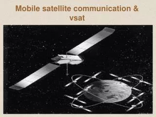
VSAT Networks due to high performance requirements, design of earth station is quite complicated. This increases the costs and the need for maintainence. Very Small Aperture Terminals (VSAT) provides a solution to this problem. The key point in VSAT networks is that either the transmitter or the receiver antenna on a satellite link must be larger. In order to simplify VSAT design, a lower performance microwave transceiver and lower gain dish antenna (smaller size) is used. They act as bidirectional earths stations that are small, simple and cheap enough to be installed in the end user's premise.