Download
1 / 1
10 likes | 210 Views
RF In. RF Out. uA. mV. Multipacting Simulations of TTF-III Coupler Components *#. L. Ge, C. Adolphsen, K. Ko, L. Lee, Z. Li, C. Ng, G. Schussman, F. Wang, SLAC, B. Rusnak, LLNL.

E N D
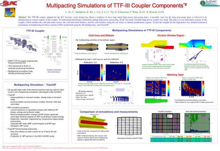
RF In RF Out uA mV Multipacting Simulations of TTF-III Coupler Components*# L. Ge, C. Adolphsen, K. Ko, L. Lee, Z. Li, C. Ng, G. Schussman, F. Wang, SLAC, B. Rusnak, LLNL Abstract: The TTF-III coupler adopted for the ILC baseline cavity design has shown a tendency to have long initial high power processing times. A possible cause for the long processing times is believed to be multipacting in various regions of the coupler. To understand performance limitations during high power processing, SLAC has built a flexible high-power coupler test stand. The plan is to test individual sections of the coupler, which includes the cold and warm coaxes, the cold and warm bellows, and the cold window, using the test stand to identify problematic regions. To provide insights for the high power test, detailed numerical simulations of multipacting for these sections will be performed using the 3D multipacting code Track3P. Multipacting Simulations of TTF-III Components TTF-III Coupler Cold Coax and Bellows Ceramic Window Region • No multipacting activities in the bellows region Electric Field Particle distribution at 100th period Particle distribution at 2nd period • Multipacting map in cold coax w/ and w/o reflection • DESY TTF-III coupler experienced long processing time • Test stand built at SLAC to evaluate processing limitations • Multipacting simulations help identify processing barriers A multipacting particle trajectory between ceramic window and taper region of inner conductor on the cold side Impact energy and MP order versus input power for two-point multipacting particles between ceramic window and cold inner conductor Coupler component test stand layout Matching Taper Delta as a function of RF input power and z axis location Delta as a function of RF input power and MP order During charging of SW cavity, reflection varies from 0% to 100 % . Partial SW field in coax shifts MP to lower order and power level. Multipacting Simulation – Track3P • 3D parallel high-order finite-element particle tracking code fordark current and multipacting simulations (developed under SciDAC) • Track3P • traces particles in resonant modes, steady state or transient fields • accommodates several emission models: thermal, field and secondary • MP simulation procedure • Launch electrons on specified surfaces with different RF phase, energy and emission angle • Record impact position, energy and RF phase; generate secondary electrons based on SEY according to impact energy • Determine “resonant” trajectories by consecutive impact phase and position • Calculate MP order (#RF cycles/impact) and MP type (#impacts /MP cycle) • Track3P benchmarked extensively • Rise time effects on dark current for an X-band 30-cell structure • Prediction of MP barriers in the KEK ICHIRO cavity • MP particle trajectory • Reflection: 0.5 • Input power level: 160KW • Order: 5th order • Impact energy: 542-544 eV • No Multipacting activities between coax pipes • High impedance coax supports MP at higher power level Comparison of simulations and measurements Track3P simulation After high power processing Electron pickup • Coax is the first component for high power processing • After initial processing, the vacuum and electron pickup signal show multipacting bands in agreement with simulations Secondary emission yield (R. Kirby) * This work was supported by DOE contract No. DE-AC02-76SF00515. # This work was performed under the auspices of the U. S. Department of Energy by the University of California, Lawrence Livermore National Laboratory under Contract No. W-7405-Eng-48.