IntelPentiumM_r4.ppt
Pentium (586) - first superscalar - included two pipelines, u and v - virtual-8086 mode ... Pentium Pro (686 or P6) - three-way superscalar ...

IntelPentiumM_r4.ppt
E N D
Presentation Transcript
Outline • History • P6 Pipeline in detail • New features • Improved Branch Prediction • Micro-ops fusion • Speed Step technology • Thermal Throttle 2 • Power and Performance
Quick Review of x86 • 8080 - 8-bit • 8086/8088 - 16-bit (8088 had 8-bit external data bus) - segmented memory model • 286 - introduction of protected mode, which included: segment limit checking, privilege levels, read- and exe-only segment options • 386 - 32-bit - segmented and flat memory model - paging • 486 - first pipeline - expanded the 386's ID and EX units into five-stage pipeline - first to include on-chip cache - integrated x87 FPU (before it was a coprocessor) • Pentium (586) - first superscalar - included two pipelines, u and v - virtual-8086 mode - MMX soon after • Pentium Pro (686 or P6) - three-way superscalar - dynamic execution - out-of-order execution, branch prediction, speculative execution - very successful micro-architecture • Pentium 2 and 3 - both P6 • Pentium 4 - new NetBurst architecture • Pentium M - enhanced P6
Pentium Pro Roots • NexGen 586 (1994) • Decomposes IA32 instructions into simplerRISC-like operations (R-ops or micro-ops) • Decoupled Approach • NexGen bought by AMD • AMD K5 (1995) – also used micro-ops • Intel Pentium Pro • Intel’s first use of decoupled architecture
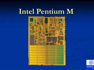
Pentium-M Overview • Introduced March 12, 2003 • Initially called Banias • Created by Israeli team • Missed deadline by less than 5 days • Marketed with Intel’s Centrino Initiative • Based on P6 microarchitechture
P6 Pipeline in a Nutshell • Divided into three clusters (front, middle, back) • In-order Front-End • Out-of-order Execution Core • Retirement • Each cluster is independent • I.e. if a mispredicted branch is detected in the front-end, the front-end will flush and retch from the corrected branch target, all while the execution core continues working on previous instructions
P6 Front-End • Major units: IFU, ID, RAT, Allocator, BTB, BAC • Fetching (IFU) • Includes I-cache, I-streaming cache, ITLB, ILD • No pre-decoding • Boundary markings by instruction-length decoder (ILD) • Branch Prediction • Predicted (speculative) instructions are marked • Decoding (ID) • Conversion of instructions (macro-ops) into micro-ops • Allocation of Buffer Entries: RS, ROB, MOB
P6 Execution Core • Reservation Station (RS) • Waiting micro-ops ready to go • Scheduler • Out-of-order Execution of micro-ops • Independent execution units (EU) • Must be careful about out-of-order memory access • Memory ordering buffer (MOB) interfaces to the memory subsystem • Requirements for execution • Available operands, EU, and write-back bus • Optimal performance
P6 Retirement • In-order updating of architected machine state • Re-order buffer (ROB) • Micro-op retirement – “all or none” • Architecturally illegal to retire only partof an IA-32 instruction • In-ordering handling of exceptions • Legal to handle mid-execution, but illegalto handle mid-retirement
PM Changes to P6 • Most changes made in P6 front-end • Added and expanded on P4 branch predictor • Micro-ops fusion • Addition of dedicated stack engine • Pipeline length • Longer than P3, shorter than P4 • Accommodates extra features above
PM Changes to P6, cont. • Intel has not released the exact length of the pipeline. • Known to be somewhere between the P4 (20 stage)and the P3 (10 stage). Rumored to be 12 stages. • Trades off slightly lower clock frequencies (than P4) for better performance per clock, less branch prediction penalties, …
Banias • 1st version • 77 million transistors, 23 million more than P4 • 1 MB on die Level 2 cache • 400 MHz FSB (quad pumped 100 MHZ) • 130 nm process • Frequencies between 1.3 – 1.7 GHz • Thermal Design Point of 24.5 watts http://www.intel.com/pressroom/archive/photos/centrino.htm
Dothan • Launched May 10, 2004 • 140 million transistors • 2 MB Level 2 cache • 400 or 533 MHz FSB • Frequencies between 1.0 to 2.26 GHz • Thermal Design Point of 21(400 MHz FSB) to 27 watts http://www.intel.com/pressroom/archive/photos/centrino.htm
Dothan cont. • 90 nm process technology on 300 mm wafer. • Provide twice the capacity of the 200 mm while the process dimensions double the transistor density • Gate dimensions are 50nm or approx half the diameter if the influenza virus • P and n gate voltages are reduced by enhancing the carrier mobility of the Si lattice by 10-20% • Draws less than 1 W average power
Bus • Utilizes a split transaction deferred reply protocol • 64-bit width • Delivers up to 3.2 Gbps (Banis) or 4.2 Gbps (Dothan) in and out of the processor • Utilizes source synchronous transfer of addresses and data • Data transferred 4 times per bus clock • Addresses can be delivered times per bus clock
Bus update in Dothan • http://www.intel.com/technology/itj/2005/volume09issue01/art05_perf_power
L1 Cache • 64KB total • 32 K instruction • 32 K data (4 times P4M) • Write-back vs. write-through on P4 • In write-through cache, data is written to both L1 and main memory simultaneously • In write-back cache, data can be loaded without writing to main memory, increasing speed by reducing the number of slow memory writes
L2 cache • 1 – 2 MB • 8-way set associative • Each set is divided into 4 separate power quadrants. • Each individual power quadrant can be set to a sleep mode, shutting off power to those quadrants • Allows for only 1/32 of cache to be powered at any time • Increased latency vs. improved power consumption
Prefetch • Prefetch logic fetches data to the level 2 cache before L1 cache requests occur • Reduces compulsory misses due to an increase of valid data in cache • Reduces bus cycle penalties
Schedule • P6 Pipeline in detail • Front-End • Execution Core • Back-End • Power Issues • Intel SpeedStep • Testing the Features • x86 system registers • Performance Testing
P6 Front-end: Instruction Fetching • IA-32 Memory Management • Classic segmented model (cannot be disabled in protected mode) • Separation of code, data, and stack into "segments“ • Optional paging • Segments divided into pages (typically 4KB) • Additional protection to segment-protection • I.e. provides read-write protection on a page-by-page basis • Stage 11 (stage 1) - Selection of address for next I-cache access • Speculation – address chosen from competing sources (i.e. BTB, BAC, loop detector, etc.) • Calculation of linear address from logical (segment selector + offset) • Segment selector – index into a table of segment descriptors, which include base address, size, type, and access right of the segment • Remember: only six segment selectors, so only six usable at a time • 32-bit code nowadays uses flat model, so OS can make do with only a few (typically four) segments • IFU chooses address with highest priority and sends it to stage two
P6 Front-end: Instruction Fetching • Stage 12-13 - Accessing of caches • Accesses instruction caches with address calculated in stage one • Includes standard cache, victim cache, and streaming buffer • With paging, consults ITLB to determine physical page number (tag bits) • Without paging, linear address from stage one becomes physical address • Obtains branch prediction from branch target buffer (BTB) • BTB takes two cycles to complete one access • Instruction boundary (ILD) and BTB markings • Stage 14 - Completion of instruction cache access • Instructions and their marks are sent to instruction buffer or steered to ID
P6 Front-end: Instruction Decoding • Stage 15-16 - Decoding of IA32 Instructions • Alignment of instruction bytes • Identification of the ends of up to three instructions • Conversion of instructions into micro-ops • Stage 17 - Branch Decoding • If the ID notices a branch that went unpredicted by the BTB (i.e. if the BTB had never seen the branch before), flushes the in-order pipe, and re-fetches from the branch target • Branch target calculated by BAC • Early catch saves speculative instructions from being sent through the pipeline • Stage 21 - Register Allocation and Renaming • Synonymous with stage 17 (a reminder of independent working units) • Allocator used to allocate required entries in ROB, RS, LB, and SB • Register Alias Table (RAT) consulted • Maps logical sources/destinations to physical entries in the ROB (or sometimes RRF) • Stage 22 – Completion of Front-End • Marked micro-ops are forwarded to RS and ROB, where theyawait execution and retirement, respectively.
Register Alias Table Introduction • Provides register renaming of integer and floating-point registers and flags • Maps logical (architected) entries to physical entries usually in the re-order buffer (ROB) • Physical entries are actually allocated by the Allocator • The physical entry pointers become a part of the micro-op’s overall state as it travels through the pipeline
RAT Details • P6 is 3-way super-scalar, so the RAT must be able to rename up to six logical sources per cycle • Any data dependences must be handled • Ex: op1) ADD EAX, EBX, ECX (dest. = EAX) op2) ADD EAX, EAX, EDX op3) ADD EDX, EAX, EDX • Instead of making op2 wait for op1 to retire, the RAT provides data forwarding • Same case for op3, but RAT must make sure that it gets the result from op2 and not op1
RAT Implementation Difficulties • Speculative Renaming • Since speculative micro-ops flow by, the RAT must be able to undo its mappings in the case of a branch misprediction • Partial-width register reads and writes • Consider a partial-width write followed by a larger-width read • Data required by the read is an assimilation of multiple previous writes to the register – to make sure, RAT must stall the pipeline • Retirement Overrides • Common interaction between RAT and ROB • When a micro-op retires, its ROB entry is removed and its result may be latched into an architected destination register • If any active micro-ops source the retired op’s destination, they must not reference the outdated ROB entry • Mismatch stalls • Associated with flag renaming
The Allocator • Works in conjunction with RAT to allocate required entries • In each cycle, assumes three ROB, RS, and LB and two SB entries • Once micro-ops arrive, it determines how many entries are really needed • ROB Allocation • If three entries aren’t available the allocator will stall • RS Allocation • A bitmap is used to determine which entries are free • If the RS is full, pipeline is stalled • RS must make sure valid entries are not overwritten • MOB Allocation • Allocation of LB and SB entries also done by allocator
PM Changes to P6 Front-End • Micro-op fusion • Dedicated Stack Engine • Enhanced branch prediction • Additional stages • Intel’s secret • Most likely required for extra functionality above
Micro-ops Fusion • Fusion of multiple micro-ops into one micro-op • Less contention for buffer entries • Similarity to SIMD data packing • Two examples of fusion from Intel documentation: • IA32 load-and-operate and store instructions • Not known for certain whether these are the only cases of fusion • Possibly inspired by MacroOps used in K7 (Athlon)
Dedicated Stack Engine • Traditional out-of-order implementations update the Stack Pointer Register (ESP) by sending a µop to update the ESP register with every stack related instruction • Pentium M implementation • A delta register (ESPD) is maintained in the front end • A historic ESP (ESPO) is then kept in the out-of-order execution core • Dedicated logic was added to update the ESP by adding the ESPO with the ESPD
Improvements • The ESPO value kept in the out-of-order machine is not changed during a sequence of stack operations, this allows for more parallelism opportunities to be realized • Since ESPD updates are now done by a dedicated adder, the execution unit is now free to work on other µops and the ALU’s are freed to work on more complex operations • Decreased power consumption since large adders are not used for small operations and the eliminated µops do not toggle through the machine • Approximately 5% of the µops have been eliminated
Complications • Since the new adder lives in the front end all of its calculations are speculative. This necessitates the addition of recovery table for all values of ESPO and ESPD • If the architectural value of ESP is needed inside of the out-of-order machine the decode logic then needs to insert a µop that will carry out the ESP calculation
Branch Prediction • Longer pipelines mean higher penalties for mispredicted branches • Improvements result in added performance and hence less energy spent per instruction retired
Branch Prediction in Pentium M • Enhanced version of Pentium 4 predictor • Two branch predictors added that run in tandem with P4 predictor: • Loop detector • Indirect branch detector • 20% lower misprediction rate than PIII resulting in up to 7% gain in real performance
Branch Prediction Based on diagram found here: http://www.cpuid.org/reviews/PentiumM/index.php
Loop Detector • A predictor that always branches in a loop will always incorrectly branch on the last iteration • Detector analyzes branches for loop behavior • Benefits a wide variety of program types http://www.intel.com/technology/itj/2003/volume07issue02/art03_pentiumm/p05_branch.htm
Indirect Branch Predictor • Picks targets based on global flow control history • Benefits programs compiled to branch to calculated addresses http://www.intel.com/technology/itj/2003/volume07issue02/art03_pentiumm/p05_branch.htm
Reservation Station • Used as a store for µops to wait for their operands and execution units to become available • Consists of 20 entries • Control portion of the entry can be written to from one of three ports • Data portion can be written to from one of 6 available ports • 3 for ROB • 3 for EU write backs • Scheduler then uses this to schedule up to 5 µops at a time • During pipeline stage 31 entries that are ready for dispatch are then sent to stage 32
Cancellation • Reservation Station assumes that all cache accesses will be hits • In the case of a cache miss micro-ops that are dependant on the write-back data need to be cancelled and rescheduled at a later time • Can also occur due to a future resource conflict
Retirement • Takes 2 clock cycles to complete • Utilizes reorder buffer (ROB) to control retirement or completion of μops • ROB is a multi-ported register file with separate ports for • Allocation time writes of µop fields needed at retirement • Execution Unit write-backs • ROB reads of sources for the Reservation Station • Retirement logic reads of speculative result data • Consists of 40 entries with each entry 157 bits wide • The ROB participates in • Speculative execution • Register renaming • Out-of-order execution
Speculative Execution • Buffers results of the execution unit before commit • Allows maximum rate for fetch and execute by assuming that branch prediction is perfect and no exceptions have occurred • If a misprediction occurs: • Speculative results stored in the ROB are immediately discarded • Microengine will restart by examining the committed state in the ROB
Register Renaming • Entries in the ROB that will hold the results of speculative µops are allocated during stage 21 of the pipeline • In stage 22 the sources for the µops are delivered based upon the allocation in stage 21. • Data is written to the ROB by the Execution Unit into the renamed register during stage 83
Out-of-order Execution • Allows µops to complete and write back their results without concern for other µops executing simultaneously • The ROB reorders the completed µops into the original sequence and updates the architectural state • Entries in ROB are treated as FIFO during retirement • µops are originally allocated in sequential order so the retirement will also follow the original program order • Happens during pipeline stage 92 and 93
Exception Handling • Events are sent to the ROB by the EU during stage 83 • Results sent to the ROB from the Execution Unit are speculative results, therefore any exceptions encountered may not be real • If the ROB determines that branch prediction was incorrect it inserts a clear signal at the point just before the retirement of this operation and then flushes all the speculative operations from the machine • If speculation is correct, the ROB will invoke the correct microcode exception handler • All event records are saved to allow the handler to repair the result or invoke the correct macro handler • Pointers for the macro and micro instructions are also needed to allow the program to resume after completion by the event handler • If the ROB retires an operation that faults, both the in-order and out-of-order sections are cleared. This happens during pipeline stages 93 and 94
Memory Subsystem • Memory Ordering Buffer (MOB) • Execution is out-of-order, but memory accesses cannot just be done in any order • Contains mainly the LB and the SB • Speculative loads and stores • Not all loads can be speculative • I.e. a memory-mapped I/O ld could have unrecoverable side effects • Stores are never speculative (can’t get back overwritten bits) • But to improve performance, stores are queued in the store buffer (SB) to allow pending loads to proceed • Similar to a write-back cache