Download
1 / 5
50 likes | 167 Views
The Smartdesk is packaged ready to be assembled. Included are a Master Parts and Panel List showing diagrams of all parts and hardware required for assembly. If you need additional assistance or information, please contact Technical Service at 410-922-6005. To check more products, get in touch with them at http://www.smartdesks.com/printer-cabinets.asp

E N D
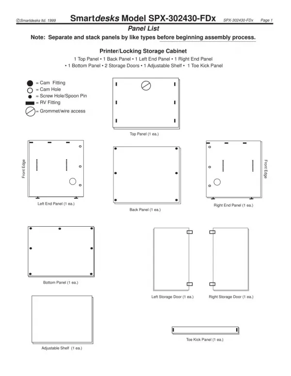
Smartdesks Model SPX-302430-FDx Panel List Note: Separate and stack panels by like types before beginning assembly process. c Smartdesks ltd. 1999 SPX-302430-FDx Page 1 Printer/Locking Storage Cabinet 1 Top Panel • 1 Back Panel • 1 Left End Panel • 1 Right End Panel • 1 Bottom Panel • 2 Storage Doors • 1 Adjustable Shelf • 1 Toe Kick Panel = Cam Fitting = Cam Hole = Screw Hole/Spoon Pin = RV Fitting = Grommet/wire access Top Panel (1 ea.) Front Edge Front Edge Left End Panel (1 ea.) Right End Panel (1 ea.) Back Panel (1 ea.) Bottom Panel (1 ea.) Left Storage Door (1 ea.) Right Storage Door (1 ea.) Toe Kick Panel (1 ea.) Adjustable Shelf (1 ea.)
Smartdesks Model SPX-302430-FDx SPX-302430-FDx Page 2 The Smartdesk is packaged ready to be assembled. Included is a Master Parts and Panel List showing diagrams of all parts and hardware required for assembly. Please note, improper installation may void Smartdesk warranty. To install correctly follow the enclosed instructions. If you need additional assistance or information please contact Technical Service at 410-922-6005. c Copyright Smartdesks ltd. 1999. All rights reserved. Hardware Inventory Sheet 1 person is needed to assemble Smartdesks Storage and Support Components: Printer/Locking Storage Cabinet Model SPX-302430-FDx and SPX-362430-FDx Unpack Parts and Hardware: Parts and panels will vary according to Smartdesks model. See Parts & Panels List and Hardware Inventory Sheet. Please verify all parts and quantities prior to assembly. Contact the factory if your quantities are incomplete. Note: All panels are predrilled ready for assembly. Tools needed for assembly: Power drill with #2 Phillips screwdriver bit and regular #2 Phillips screwdriver. The following diagram shows the contents of the hardware bag. Contents of Hardware Bag : (quantities for each components - multiply by number of components) extra hardware parts packaged to account for possible loss during shipping. 10 ea. - Cam Pins push through holes in panels. (Side, Back, and Bottom Panels) 2 ea.- Earthquake Pins for Adjustable Shelf (front holes) 2 ea.- Shelf Spoon Pins for Adjustable Shelf (rear holes) Smartdesks have been designed and tested as an ergonomi- cally correct and space saving unit. For more information on this and other Smartdesks products, call 1-800-770-7042 or visit our website at http://www.smartdesks.com 6 ea. - Hinge Plates 6 ea. - Hinge Plate Screw Cover Caps to cover Hinge Plate Screws Smartdesks Storage and Support Components: SPX-302430-FDx/SPX-362430-FDx Printer/Locking Storage Cabinet
SPX-302430-FDx Page 3 c Smartdesks ltd. 1999 Figure 1 STEP 1 - Top & Side Panel Assembly Figure 4 In a clean work area lay Top Panel with top facing down on the floor on cardboard or carpet/packing quilt. (Fig. 1) STEP 2 - Back Panel To Sides Assembly Figure 2 NOTE: 2 person assembly required for proper fit. Slide Back Panel into position between two Side Panels matching the cam fittings to the holes at top. It is necessary for 2 people to accomplish this assembly. Vertical panels cannot be left standing unsupported (Fig.4) Insert top 2 Cam Pins through Left and Right Side Panels into cam fittings. (Fig. 5) Start at the top cam of each end panel when inserting Cam Pins and move down each end panel alternating as Cam Pins are inserted. Make sure arrows on Cam Pins are facing out (3 pm clock position). Lift and place Left Side Panel into 90overtical position with fittings facing in. While holding right panel in ver- tical position, match RV Fittings to one another and snap panel into place. Use power drill to tighten the screw contained in the RV Fitting. (Fig.2) Each RV Fitting contains a screw to lock the hardware once the panels have been snapped into place. Warranty is void if all locking screws have not been tightened. RV Fittings come preinstalled in panels and are equally spaced along Top edge. Tighten all remaining RV Fittings along panel edge. (Fig.3) Repeat STEP 1 for the installation of the Left Side Panel. Figure 5 Figure 3
SPX-302430-FDx Page 4 c Smartdesks ltd. 1999 STEP 2 - Back Panel To Sides Assembly (cont.) STEP 3 - Bottom Panel Assembly NOTE: 1 person assembly required for proper fit. NOTE: 1 person assembly is required for proper fit. Tighten about 1/4 turn with screwdriver until it locks into place.(Fig. 6) Repeat this step for remaining Cam Pins. The Cam Pin is a steel to steel assembly which ensures heavy duty strength when assembled. (Once Back Panel is secured to Left and Right Side Panels, the “shell” of the unit is assembled. (Fig. 7)) The Bottom Panel is not adjustable. Make sure arrows on cams are facing out. With cabinet laying on its back, push 2 Cam Pins through one side. Align predrilled hole on Bottom Panel with Cam Pins that have been pushed through. Then slide the Bottom Panel into position. Align holes and Cam Pins. Slide Bottom Panel in place. (Fig. 9) For opposite side, Bottom Panel is already set in place. Insert Cam Pins through holes into Bottom Panel. Tighten only the left side of Cam Fittings BEFORE mounting the Toe Kick Panel. (Fig. 10) Figure 6 Figure 9 Cam pin is inserted through panel into preinstalled fitting. Check to verify that arrow is pointing perpendicular to pin when Cam is locked. Figure 7 Figure 10 STEP 4 - Toe Kick Assembly NOTE: 1 person assembly is required for proper fit. Figure 8 Figure 11 While holding Toe Kick Panel with the front facing up, match RV Fittings to one another and snap the left side of the Toe Kick Panel into place. Left side of the Toe Kick Panel is now temporarily mounted. (Fig. 11) Figure 8 Smartdesks Storage & Support Component SPX -302430-FDx/Fxx Unit Back & Side Panels Assembled
SPX-302430-FDx Page 5 c Smartdesks ltd. 1999 STEP 4 - Toe Kick Assembly (cont.) STEP 6 - Adjustable Shelf NOTE: 1 person assembly is required for proper fit. NOTE: 1 person assembly is required for proper fit. Figure 12 Figure 14 2 sets of predrilled holes in side panels are used for the Adjustable Shelf. Insert Earthquake Pins. Push 1 Earthquake Pin in front hole of Left and Right Side Panel. Insert Shelf Spoon Pins. Push 1 Shelf Spoon Pin in matching level rear holes of Left and Right Side Panel. (Fig. 14) Gently spread the Bottom and Right Side Panels apart so that the RV Fittings of the right side of the Toe Kick Panel can be matched and snapped into place. (Fig. 12) It is necessary to tighten the last 2 Cam Fittings on the bottom and tighten the RV Fittings on the Toe Kick Panel. STEP 5 - Flip SPX Unit 180oto Upright Position Figure 15 NOTE: 2 persons required for this step. Roll SPX unit on its back then to its upright position. (Fig. 13) Slide Adjustable Shelf into place and rest on top of pins. (Fig. 15) Adjustable Shelf should be parallel to Top Panel. STEP 7 - Installation of Storage Door Lift and place Storage Door to match hinge fittings of Right Side Panel. Snap hinge fittings together. (Fig.16) Close Storage Door. Figure 16 Figure 13