Experiment 8. Network Simulators : OPNET , NS
Experiment 8. Network Simulators : OPNET , NS. April 18, 2006. Network systems Lab. Kyuho Son ( skio@netsys.kaist.ac.kr ). Overview. OPNET Overview A graphical network simulator mainly used for simulations of wired/wireless communications networks and information technology.

Experiment 8. Network Simulators : OPNET , NS
E N D
Presentation Transcript
Experiment 8. Network Simulators : OPNET, NS April 18, 2006. Network systems Lab. Kyuho Son (skio@netsys.kaist.ac.kr)
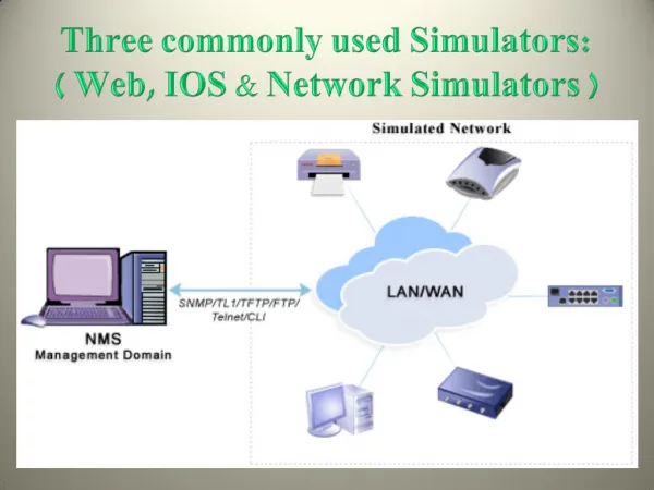
Overview • OPNET Overview • A graphical network simulator mainly used for simulations of wired/wireless communications networks and information technology. • Although OPNET is very expensive, it has innumerable libraries. • Made by MIL3, http://www.opnet.com/ • NS-2 Overview • A text-based network simulator mainly used for simulations of Internet. • It is mainly used for simulations of TCP, AQM, DiffServ, IntServ, Wireless Ad-hoc Network. • TCP : Tahoe, Reno, Newreno, SACK, Vegas • AQM : Drop Tail, RED, FRED, REM, DRR, SFQ • Wireless Ad-hoc Network modules are developed in the name of Monarch Project, http://www.monarch.cs.rice.edu/ • Made by various researchers, http://www.isi.edu/nsnam/ns/
OPNET Key Features • Object orientation • Specialized in communication networks and information system • Hierarchical models • Graphic specification • Flexibility to develop detailed custom models • Automatic generation of simulation • Application-specific statistics • Integrated post-simulation analysis tools • Interactive analysis • Animation
Typical Applications • Standard-based LAN and WAN performance modeling • Internetworking planning • Research and development in communications architecture and protocol • Mobile packet radio networks : 3GPP, 3GPP2 • Satellite networks
Organization • Project editor • Node editor • Process editor • Link model editor • Packet format editor • ICI editor • PDF editor • Probe/Simulation • Analysis/Filter
Project Editor • The main staging area for creating a network simulation • You can create a network model using models from the standard library, collect statistics about the network, run the simulation, and view the results.
Node Editor • It is used to define the behavior of each network object. • Behavior is defined using different modules. • Modules are connected via packet streams or statistic wires.
Process Model Editor • It is used to create process models, which control the underlying functionality of the node models created in the Node Editor. • Process models are represented by finite state machines (FSMs), and are created with icons that represent states and lines that represent transitions between states.
NS-2 Key Features • Composition of two Object Oriented Languages • OTcl and C++ • Control/Data Separation • OTcl(Control) : Used for scripting simulation topology • C++(Data) : Used for programming each object in simulation topology • Text-based Network Simulator • You have to code everything you need. • GUI interface is not supported for creating topology and simulation. • Many Experimental Algorithms are Implemented in NS-2 by Researchers. Helpful for research
C++ and OTcl Separation • C++ for “data” • Per packet action • OTcl for “Control” • Periodic or triggered action • Compromise between composibility & speed of simulation. • To minimize execution time of simulation, C++ should be deployed for describing details of operation. • You can easily change network topology by changing OTcl script. You don’t have to recompile if you didn’t modified internals of network objects. This maximizes composibility. • Learning and debugging • Because two different languages are mixed, you should learn two languages • Concurrent debugging two languages is generally difficult.
Simplified User’s View of NS-2 • Step 1 : Make a OTcl script for simulation. • Step 2 : OTcl script will be run by OTcl interpreter. In fact, NS-2 shell is basically OTcl interpreter that has access to NS Simulator Library. • Step 3 : Simulation results are now at hand. • Step 4 (optional) : You can analyze the results and animate simulation results using NAM.
C++ and OTcl : The Duality • The network component objects in the data path are written and compiled using C++. • These compiled objects are made available to the OTcl interpreter through an OTcl linkage that creates a matching OTcl object for each of the C++ objects • In this way, the controls of the C++ objects are given to OTcl.
Simple Simulation Script- creating a simulator object • #Create a simulator object • set ns [new Simulator] • #Define different colors for data flows (for NAM) • $ns color 1 Blue • $ns color 2 Red • #Open the NAM trace file • set nf [open out.nam w] • $ns namtrace-all $nf • #Define a 'finish' procedure • proc finish {} { • global ns nf • $ns flush-trace • #Close the NAM trace file • close $nf • #Execute NAM on the trace file • exec nam out.nam & • exit 0 • }
Simple Simulation Script- creating nodes • #Create four nodes • set n0 [$ns node] • set n1 [$ns node] • set n2 [$ns node] • set n3 [$ns node] • #Create links between the nodes • $ns duplex-link $n0 $n2 2Mb 10ms DropTail • $ns duplex-link $n1 $n2 2Mb 10ms DropTail • $ns duplex-link $n2 $n3 1.7Mb 20ms DropTail • #Set Queue Size of link (n2-n3) to 10 • $ns queue-limit $n2 $n3 10 • #Give node position (for NAM) • $ns duplex-link-op $n0 $n2 orient right-down • $ns duplex-link-op $n1 $n2 orient right-up • $ns duplex-link-op $n2 $n3 orient right • #Monitor the queue for link (n2-n3). (for NAM) • $ns duplex-link-op $n2 $n3 queuePos 0.5
Simple Simulation Script- creating FTP/TCP & CBR/UDP connections • #Setup a TCP connection • set tcp [new Agent/TCP] • $tcp set class_ 2 • $ns attach-agent $n0 $tcp • set sink [new Agent/TCPSink] • $ns attach-agent $n3 $sink • $ns connect $tcp $sink • $tcp set fid_ 1 • #Setup a FTP over TCP connection • set ftp [new Application/FTP] • $ftp attach-agent $tcp • $ftp set type_ FTP • #Setup a UDP connection • set udp [new Agent/UDP] • $ns attach-agent $n1 $udp • set null [new Agent/Null] • $ns attach-agent $n3 $null • $ns connect $udp $null • $udp set fid_ 2
#Setup a CBR over UDP connection • set cbr [new Application/Traffic/CBR] • $cbr attach-agent $udp • $cbr set type_ CBR • $cbr set packet_size_ 1000 • $cbr set rate_ 1mb • $cbr set random_ false • #Schedule events for the CBR and FTP agents • $ns at 0.1 "$cbr start" • $ns at 1.0 "$ftp start" • $ns at 4.0 "$ftp stop" • $ns at 4.5 "$cbr stop" • #Call the finish procedure after 5 seconds of simulation time • $ns at 5.0 "finish" • #Print CBR packet size and interval • puts "CBR packet size = [$cbr set packet_size_]" • puts "CBR interval = [$cbr set interval_]" • #Run the simulation • $ns run
3. Prerequisite for the experiment,Pre and Main Lab Report Problems,
Prerequisite for the experiment • 1.Please install NS-2 in your own Linux machine. • 2. Please make yourself familiar with OTcl [4], [5]. • 3.Please(x100) read [3] and be a skillful NS-2 user. • 4. Please read [7] so that you can know how “RED”operates. • 5. Please read [8] so that you can know why “DRR with LQD” is superior to “RED”. Please read at least two sections 2.2 and 3.2. (NS by example)
Pre Lab Report Problems • Problems • 1. Describe the congestion control mechanism of TCP Reno. You may find several terminology in the literature such as slow start mode, congestion avoidance, fast retransmit, and fast recovery. Explain these terms in detail. What is the difference between TCP Reno and TCP Newreno? • 2. Explain WFQ (Weighted Fair Queueing) in detail. • 3. Summarize the simulation results of the following network. (End-to-End Delay Performance should be plotted.)
Main Lab Report Problems • Problems • 1. Summarize and discuss the simulation results obtained by NS-2 in the experiment. • 2. Explain the relation between received bandwidth and RTT (Round Trip Time) when TCP is deployed. [9], [10] • 3. Compare AQM schemes. To be specific, explain the operation of “RED [7]” and “DRR with LQD [8]” and compare them.
References • [1] OPNET Modeling Concepts • [2] The Network Simulator – ns-2, http://www.isi.edu/nsnam/ns/ • [3] NS by Example, http://nile.wpi.edu/NS/ • [4] A draft for Tcl/Tk book, ftp://ftp.scriptics.com/pub/welch • [5] OTcl Tutorial, ftp://ftp.tns.lcs.mit.edu/pub/otcl/doc/tutorial.html • [6] The ns Manual, http://www.isi.edu/nsnam/ns/ns-documentation.html • [7] S. Floyd, V. Jacobson, “Random early detection gateways for congestion avoidance”, IEEE/ACM Transaction on Networking, Volume: 1 Issue: 4 , Aug. 1993, Page(s): 397 -413 • [8] B. Suter, T.V. Stiliadis, A.K. Choudhury, “Buffer management schemes for supporting TCP in gigabit routers with per-flow queueing”, IEEE Journal on Selected Areas in Communications, Volume: 17 Issue: 6 , June 1999, Page(s): 1159 -1169 • [9] M. Mathis, J. Semke, J. Mahdavi, T. Ott, “The Macroscopic Behavior of the TCP Congestion Avoidance Algorithm”, ACM Computer Communication Review, Volume: 27, Issue: 3, July 1997. • [10] J. Padhye, V. Firoiu, D. Towsley, J. Kurose, “Modeling TCP Throughput: A Simple Model and its Empirical Validation”, IEEE/ACM Transaction on Networking, Volume: 8, Issue: 2, April 2000, Page(s): 133 -145.