WATERPROOF FLEXIBLE CUTOFF WALL
690 likes | 733 Views
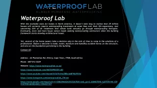
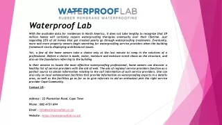
Australian varieties of trees and shrubs use large amounts of water in normal conditions. This problem (known as Matric Suction), especially combined with reactive (clay) soils can cause substantial damage to the foundation of buildings, walls, pathways and roads. For more information, please contact us now. Root Barrier, Unit2, 44 Telford St, Virginia Qld 4014, AU, Phone: 1300 13 66 44, http://rootbarrier.com.au/

WATERPROOF FLEXIBLE CUTOFF WALL
E N D
Presentation Transcript
ROOT BARRIER ™ PRESENTATION WATERPROOF FLEXIBLE CUTOFF WALL www.rootbarrier.com.au
ROOT BARRIER ™ PRESENTATION c Click on these links to skip to different parts of the presentation. Alternatively view the presentation as normal. Product Overview \ Matric Suction Sodium Bentonite (UPGI) Under Path Growth Inhibitor Design & Installation Guidelines Below are links to supplementary documents CONTAINED ON OUR WEBSITE if you do not have internet access these links will not work. You can request a CD version by contacting ROOT BARRIER ™ on 1300 136644. Technical Specs – includes technical information & product specification. Material Safety Data Sheet for Sodium Bentonite. BSA Advisory Guidelines and Fact Sheet for Contractors and Home Owners. BSA Fact Sheet on Subsidence – Page 1, Page 2, Page 3, Page 4. BCC Natural Assets Law BCC Natural Assets Law Summary www.rootbarrier.com.au
PRODUCT OVERVIEW c Root barrier has many applications Civil works; Back of kerb, bio swales, protecting infrastructure. New houses; Stabilizing reactive clay under foundations, Established houses; Buildings cracked by clay shrinkage can be restored by isolating and stabilizing the moisture under the building. Water proof cutoff walls; Stopping contamination migration through the soil. Landscaping applications; Root group separation, hardscape protection. Services protection; New innovation is pipe wrap to provide an insulation layer around pipes and conduits. www.rootbarrier.com.au
PRODUCT OVERVIEW c Australian varieties of trees and shrubs use large amounts of water in normal conditions. This problem (known as Matric Suction), especially combined with reactive (clay) soils can cause substantial damage to the foundation of buildings, walls, pathways and roads. After damage has occurred underpinning of footings and more costly repairs (even the most drastic demolition) is often the only answer. HOME www.rootbarrier.com.au
PRODUCT OVERVIEW c The Solution - The cut-off wall. So what can be done to prevent damage in the First place, or after the event to make sure it Doesn’t re-occur. The proven method is to construct a cut-off wall. The cut-off wall effectively prevents tree roots and also moisture movement, thus stabilising the soil, and clay contraction and expansion under the footing. HOME www.rootbarrier.com.au
PRODUCT OVERVIEW c Traditionally the cut-off wall has comprised of a 300mm trench filled with reinforced concrete usually at a depth between 1 and 2 metres. These are generally difficult and thus very expensive to construct. Introducing Root Barrier - the cost effective way to prevent root and moisture damage. Root Barrier is the answer for moisture stabilisation. This light weight plastic shield (just 0.75mm thick) is especially designed to form an impenetrable barrier against tree roots and excessive moisture and damp. HOME www.rootbarrier.com.au
PRODUCT OVERVIEW c Root Barrier is placed in a narrow trench, which is dug around the building, normally to a depth of 1 to 2 metres depending on soil type. The narrowness of this trench means far less mess and refill. The trench is located 1 to 2 metres from the wall of the building. This effectively extends the foundations on which the building sits. This impermeable barrier acts as a cut-off wall, stopping the moisture leaching away from under the buliding. The Root Barrier prevents moisture moving sideways, through the soil. Very little moisture loss can take place, and thus future movement from this cause is eliminated. HOME www.rootbarrier.com.au
PRODUCT OVERVIEW c • WHY ROOT BARRIER™? • ROOT BARRIER ™ is a specially engineered waterproof cut-off wall. • IT’S WATERPROOF: ROOT BARRIER ™ is the answer for moisture stabilisation. • IT’S FLEXIBLE: Root Barrier has a 700% elongation and is able to handle hydrostatic pressure resulting from moisture stabilization, root barrier insulates the protected area. In the dry period the reactive clay out side the protected area will dry and shrink away from the cutoff wall, “RIGID CUTOFF WALLS WILL BREAK AND FAIL” while root barriers 700% elongation is able to handle these naturally occurring variations. • SODIUM BENTONITE is a vital part of the installation process. Sodium Bentonite is used to seal the bottom of the trench and bind the bottom of the root barrier to the undisturbed soil. HOME www.rootbarrier.com.au
MATRIC SUCTION, WHAT IS IT? c Matric suction is the pressure dry soil exerts on the surrounding soils to equalise the moisture content in the overall block of soil. Matric suction conditions in the soil profile (H site) were obtained through steady state unsaturated seepage analyses. The initial matric suction profile is the same, suction varied from 409 kPa at tree root to 49 kPa at lower boundary of the soil domain. The contours of changes in matric suction are presented in Fig. 11. The closer to the tree, the more change in suction is observed. The results of stress deformation analysis are shown in Fig 14 as contours of vertical displacement. A maximum foundation settlement of 80mm and minimum settlement of 25 mm was observed. A maximum settlement in the soil profile took place at tree location and decrease with horizontal distance and depth. Fig10. Illustration of Example 2 Fig 11. Contours of Final Matric Suction (kPa) Fig 14. Contours of vertical displacements (mm) HOME Includes Extracts of Proceedings of Geo-institute Shallow Foundations and Soil Properties Committee sessions at the ASCE 2001 Civil Engineering Conference. (2001). Expansive Clay Soils and Vegetative Influence on Shallow Foundations (pp. 36 - 37). Houston: American Society of Civil Engineers. www.rootbarrier.com.au Page 7 of 10 (Overview)
c AS2870 – 2011 EXTRACTREVISED STANDARD INCLUDES TREE EFFECT Root Barrier for Moisture Control Length Sufficient to protect the structure from the effects of moisture change in the soil. BSA guidelines consider the following distances as reasonable. Structures closer than these distances to trees must be protected from, or be specially engineered to withstand the effect of the tree/s. Height of Tree(h) Distance from house (d) d = 1 h for class H and M sites. d = 1.5 h for class E sites. d = 2 h for rows or groups of trees. What does this mean? The depth of ROOT BARRIER ™ / moisture cutoff wall for protecting foundations is determined by the soil test data, and depths of 2, 3 and 4m are not unusual.
MATRIC SUCTION, WHAT IS IT? c An example of bad design when repairing failed foundations. This building has been repaired by filling and painting obvious cracking which occurred during a dry spell. After two weeks of heavy rain edge heave occurred under the building foundations. The results are obvious. Had ROOT BARRIER™ been installed as part of the initial repair the moisture content would be stable and the edge heave would not have occurred. HOME www.rootbarrier.com.au
MATRIC SUCTION, WHAT IS IT? c Examples To the left are two examples of damage that can be caused by Matric Suction. Due to variations in moisture content under the slab the corners of the structure have dropped down as the clay shrinks. Note:This property was underpinned 3 years prior without root barrier. ROOT BARRIER™ is now being installed as part of the remedial works to stabilise the house and the underpinning. HOME Page 9 of 10 (Overview) www.rootbarrier.com.au
MATRIC SUCTION, WHAT IS IT? c HOW DO WE MINIMISE THE SHRINKAGE OF REACTIVE CLAY? By placing a 1.5 to 2 metre root proof and waterproof wall around the structure that we wish to protect. This will create an island effect and keep the change in moisture content to a minimum. Root barrier will effectively disconnect the tree from the moisture under the slab. ROOT BARRIER is a flexible waterproof Cut-off wall which will achieve both goals of stabilising the clay an keeping the tree roots away. HOME www.rootbarrier.com.au
EXAMPLES OF SUCCESSFULL REMEDIATION c ANNERLEY STATE SCHOOL, JUNCTION RD — TWO JOBS JOB 1 — These two photos show a neighbouring property effected by school fig trees, Root barrier installed after Ministerial intervention in the dispute. Installed 2003 customer happy. HOME www.rootbarrier.com.au
EXAMPLES OF SUCCESSFULL REMEDIATION c ANNERLEY STATE SCHOOL, JUNCTION RD — CONTINUED JOB 2 — place Root Barrier around school swimming pool to stabilize foundations, fourth photo shows crack in brick wall is closed and stable. Installed 2003 customer happy. HOME www.rootbarrier.com.au
EXAMPLES OF SUCCESSFULL REMEDIATION c Private house, Frank Crowther, 42 Newcastle, Fairfield. House cracked by moisture movement due to Jacaranda tree. Remediation job completed 1993. House was renovated and landscaped last year. Photo of brick wall shows crack is still closed after 17 years. Custom happy. HOME www.rootbarrier.com.au
SODIUM BENTONITE c • Sodium bentonite is a naturally occurring clay material composed predominantly of the active constituent montmorillonite. On exposure to water, bentonite exhibits high swelling properties. Use is made of this in the sealing of porous soils where the swollen mass fills the voids and binds the soil particles to create an impermeable sea. Sodium bentonite is best suited to incorporation in coarse textured soils of clay content less than 10% because of the relatively easy workability. In high clay soils, incorporation is more difficult, both with respect to the placing of sodium bentonite and to ensuing compaction. Sodium bentonite is a vital part of the installation process. Sodium Bentonite is used to seal the bottom of the trench and bind the bottom of the root barrier to the undisturbed soil. HOME www.rootbarrier.com.au
c UPGI – UNDER PATH GROWTH INHIBITOR A simple measure that ensures you’ll double the life expectancy of your concrete paths around trees. HOW IT WORKS Under concrete moisture is trapped naturally, this provides a food source for the tree. Tree roots find the food and transport it back to the tree, the root that finds the most food grows the biggest. Root Barrier™ Under Path Growth Inhibitor creates a 50mm deep zone under the structure which is outside the pH range that trees like to feed on. Roots in this immediate area will not develop to damage the path. The other roots will find a more suitable food source allowing them to support and feed the plant. This product is 100% natural with no manufactured chemicals and the same salinity as sea water. The product is stabilised to prevent active components leaching from under the path. DPI tested, certifying the product meets EPA guidelines protecting local environment. Not dangerous to handle in normal circumstances, MSDS available. INSTALLATION 1. Clear the damaged section, remove existing roots in the vicinity and prepare the subgrade as normal, 2. Pour the dry Under Path Growth Inhibitor on to the exposed subgrade and spread with a rake at a ratio of 10 Kg per m2 of subgrade. 3. Continue to lay the new path as normal. RESULT 50 mm deep zone immediately below the treated area will have a pH level outside the range required by the tree. HOME www.rootbarrier.com.au
UPGI - PRODUCT ASSESSMENT REPORT SUMMARY 16 Aug. 2010 c Root Barrier’s Under Path Growth Inhibitor has undergone preliminary testing through DEEDI (Department of Employment, Economic Development and Innovation). Below is a summary of the report prepared by Matt Roche Acting senior research scientist, Agri-Science Queensland. Objectives To monitor the pH and electrical conductivity/salinity (EC) of the trial site prior toand following the application of the root growth inhibitor treatment by the Client. The collected data will be provided to the Client within this, a preliminary report (16 Aug. 2010) and a final report (7 Jun. 2011). Plate 1. Photos taken 2 August 2010 of (a) sample location A, under the current footpath and (b) sample location B, adjacent to the footpath under the turf profile. (a) (b) Sample A Sample A Sample A Sample B HOME www.rootbarrier.com.au
UPGI - PRODUCT ASSESSMENT REPORT SUMMARY 16 Aug. 2010 c Results -DEEDI soil testing Results for testing on 8 June (Prior to placing treatment) and 2 August 2010 (Post treatment) using TPS smartCHEM-LAB meter. Electrical Conductivity (EC) is a convenient method for measuring soil salinity. The bar charts show June soil samples in Black and August samples in Green. The graph below shows that the Under Path Growth Inhibitor did not leach into the surrounding environment. HOME www.rootbarrier.com.au
c DESIGN GUIDELINES HERE ARE LINKS TO DESIGN & INSTALLTION GUIDELINES FOR TYPICAL ROOT BARRIER ™ APPLICATIONS WITHIN THE PRESENTATION. Design & Installation Guidelines – Moisture Control (inc Hydration System) Design & Installation Guidelines – Moisture Control • Design & Installation Guidelines – As Part of a Foundation • Design & Installation Guidelines – For Contaminated Sites Design & Installation Guidelines – Roads Design & Installation Guidelines – Trees Design & Installation Guidelines – Underground Tanks Design & Installation Guidelines – UPGI – Under Path Growth Inhibitor Design & Installation Guidelines – Root Barrier as a Pipe Wrap • Design & Installation Guidelines – Surface Finish Options for Root Barrier • Links to installation drawings CONTAINED ON OUR WEBSITE if you do not have internet access these links will not work. You can request a CD version by contacting ROOT BARRIER ™ on 1300 136644: Moisture Control, Moisture Control with Hydration pipe, Roads (Option A, Option B), Trees, Foundation, Underground Tanks, Pipe Wrap. • Links to supplementary documents CONTAINED ON OUR WEBSITE: Technical Specs , MSDS for Sodium Bentonite. • BSA Advisory Guidelines, Subsidence Fact Sheet Page 1, Page 2, Page 3, Page 4. • BCC Natural Assets LawBCC Natural Assets Law Summary www.rootbarrier.com.au HOME
Design & Installation Guidelines - Curtain Wall Moisture Control (inc Hydration System) c • SIX CRITICAL POINTS TO SOLVE PROBLEMS WITH • TREE ROOTS, MOISTURE AND REACTIVE SOILS 1. PLACEMENT: Normal placement of the barrier is to locate it around the structure, out from and parallel to the footings of the structure. Try not to surround the tree. Our preferred method is placing the root barrier along beside the building, path, road etc so that the tree roots cannot gain access to the structure. Root barrier works as a waterproof seal protecting the soil under the structure from moisture loss laterally. The structure prevents loss of moisture vertically and so the moisture content of the soil can be stabilised and will stay reasonably constant. After installation the soil under the building can be rehydrated to return it to the moisture content that it was when the building was built Guidelines Index HOME www.rootbarrier.com.au
Design & Installation Guidelines - Curtain Wall Moisture Control (inc Hydration System) c TREE CARE • Working in from the ‘Drip Line’ (the edge of the leaves) the closer you get to the trunk the more risk you have of damaging or destabilising the tree. • 50% of the distance from the drip line to the trunk of the tree is regarded as the closest you can go without major risk to the plant’s health. Consult an arborist if it is necessary to cut closer. 2. Area of good soil that the plant will require to live a healthy life may be calculated by multiplying the radius of the mature plant canopy by r2 x .3m. The answer will give you the cubic volume of good soil required. If works require the ground surface area is not available for the plant, special pits filled with quality soils, drainage etc may provide the answer. Guidelines Index HOME www.rootbarrier.com.au
c Design & Installation Guidelines - Curtain Wall Moisture Control (inc Hydration System) 3. Depth Depth is determined by a civil engineer’s assessment of “the zone of influence” in the soil. In “normal” reactive clay depths between 1500mm and 4 metres may be expected. on the other hand if you strike rock at 700mm, the moisture cannot move through it then that is deep enough. 4. Seal Sodium Bentonite is used to seal the bottom of the trench and bind the bottom of the root barrier to the undisturbed soil. In summary take the barrier down to soil that nothing will move through and bind the root barrier to it. 5. Length Sufficient to protect the structure from the effects of moisture change in the soil. BSA guidelines consider the following distances as reasonable. Structures closer than these distances to trees must be protected from, or be specially engineered to withstand the effect of the tree/s. Height of Tree(h) Distance from house (d) d = 1 h for class H and M sites. d = 1.5 h for class E sites. d = 2 h for rows or groups of trees. www.rootbarrier.com.au Guidelines Index
c Design & Installation Guidelines - Curtain Wall Moisture Control (inc Hydration System) 6. Top Finish Root Barrier must be finished above the ground or sealed into concrete so that roots cannot grow over the top of it. See options below. HOME www.rootbarrier.com.au Guidelines Index
Design & Installation Guidelines - Curtain Wall Moisture Control (inc Hydration System) c INSTALLATION SYSTEM 1.Dig a trench a depth of 2m (unless noted otherwise), insert ROOT BARRIER. Ensure 50mm of root barrier is left above finished ground height (this is to allow for settlement and may be trimmed off later). 2. Trim exposed roots to leave a clean cut. Treat with fungicide if required. Guidelines Index HOME www.rootbarrier.com.au
Design & Installation Guidelines - Curtain Wall Moisture Control (inc Hydration System) c INSTALLATION SYSTEM contd 3. Fill the base of the trench with a 50-100mm layer of Bentonite, then backfill to 50% of trench depth using spoil from the trench. Pipe Crossings. Ideally cut all services, lay Root Barrier and cut small holes for penetrations to reinstate services, sealing crossings with sodium bentonite. Guidelines Index HOME www.rootbarrier.com.au
Design & Installation Guidelines - Curtain Wall Moisture Control (inc Hydration System) c INSTALLATION SYSTEM contd 4. Place a 60Ø slotted hydration pipe and then back fill the balance with soil. The hydration pipe should start 3.0m from uphill end of trench with 200mm of pipe above ground. The pipe is to drop vertically and turn 90 degrees finishing 3.0m from the end of the trench. Guidelines Index HOME www.rootbarrier.com.au
Design & Installation Guidelines - Curtain Wall Moisture Control (inc Hydration System) c INSTALLATION SYSTEM contd 5. Provide slow running water to hydration pipe and fill the trench until the ground at the lowest point becomes soggy. System will be working if some closure of cracks occurs. Repeat every second day until recovery slows. 6. Cap end of hydration pipe and bury just below surface (if problem recurs, dig up pipe end and repeat process. Guidelines Index HOME www.rootbarrier.com.au
Design & Installation Guidelines - Curtain Wall Moisture Control (inc Hydration System) c MOISTURE CONTROL BARRIER WITH HYDRATION PIPE Excavate 75mm wide trench to a depth of 2m (unless noted otherwise). Ensure that tree roots are cut without splitting or tearing. Place a layer of ROOT BARRIER™ in trench taking into account installation guidelines. Leave top of barrier exposed, 50mm above finished height. (Trim later after trench settlement ensuring finished height is such that roots cannot breach barrier). Provide a 50-100mm layer of dry sodium bentonite to the base of the trench to bind the Root Barrier system. Back fill to %50 of depth using existing soil. Place a 60Ø slotted hydration pipe and then back fill the balance with soil. The hydration pipe should start 3.0m from uphill end of trench with 200mm of pipe above ground. The pipe is to drop vertically and turn 90 degrees finishing 3.0m from the end of the trench. Provide slow running water to hydration pipe and fill the trench until the ground at the lowest point becomes soggy. System will be working if some closure of cracks occurs. Repeat every second day until recovery slows. Cap end of hydration pipe and bury just below surface (if problem recurs, dig up pipe end and repeat process. Print HOME Guidelines Index Page 8 of 8 (Moisture with Pipe) www.rootbarrier.com.au
Design & Installation Guidelines – Moisture Control c • SIX CRITICAL POINTS TO SOLVE PROBLEMS WITH • TREE ROOTS, MOISTURE AND REACTIVE SOILS 1. PLACEMENT: Normal placement of the barrier is to locate it around the structure, out from and parallel to the footings of the structure. Try not to surround the tree. Our preferred method is placing the root barrier along beside the building, path, road etc so that the tree roots cannot gain access to the structure. Root barrier works as a waterproof seal protecting the soil under the structure from moisture loss laterally. The structure prevents loss of moisture vertically and so the moisture content of the soil can be stabilised and will stay reasonably constant. After installation the soil under the building can be rehydrated to return it to the moisture content that it was when the building was built Guidelines Index HOME www.rootbarrier.com.au
Design & Installation Guidelines – Moisture Control c TREE CARE • Working in from the ‘Drip Line’ (the edge of the leaves) the closer you get to the trunk the more risk you have of damaging or destabilising the tree. • 50% of the distance from the drip line to the trunk of the tree is regarded as the closest you can go without major risk to the plant’s health. Consult an arborist if it is necessary to cut closer. 2. Area of good soil that the plant will require to live a healthy life may be calculated by multiplying the radius of the mature plant canopy by r2 x .3m. The answer will give you the cubic volume of good soil required. If works require the ground surface area is not available for the plant, special pits filled with quality soils, drainage etc may provide the answer. Guidelines Index HOME www.rootbarrier.com.au
Design & Installation Guidelines – Moisture Control c 3. Depth Depth is determined by a civil engineer’s assessment of “the zone of influence” in the soil. In “normal” reactive clay depths between 1500mm and 4 metres may be expected. on the other hand if you strike rock at 700mm, the moisture cannot move through it then that is deep enough. 4. Seal Sodium Bentonite is used to seal the bottom of the trench and bind the bottom of the root barrier to the undisturbed soil. In summary take the barrier down to soil that nothing will move through and bind the root barrier to it. 5. Length Sufficient to protect the structure from the effects of moisture change in the soil. BSA guidelines consider the following distances as reasonable. Structures closer than these distances to trees must be protected from, or be specially engineered to withstand the effect of the tree/s. Height of Tree(h) Distance from house (d) d = 1 h for class H and M sites. d = 1.5 h for class E sites. d = 2 h for rows or groups of trees. www.rootbarrier.com.au Guidelines Index
c Design & Installation Guidelines – Moisture Control 6. Top Finish Root Barrier must be finished above the ground or sealed into concrete so that roots cannot grow over the top of it. See options below. HOME www.rootbarrier.com.au Guidelines Index
Design & Installation Guidelines – Moisture Control c ROOT BARRIER™ FOR MOISTURE CONTROL Dig a narrow trench to the required depth, insert ROOT BARRIER™. Ensure Root Barrier is left 50mm above finished ground height. (This is to allow for settlement and may be trimmed off later.) Trim exposed roots to leave a clean cut, treat with fungicide if required. Back fill the base of the trench placing the layer of Sodium Bentonite, then backfill using spoil from the trench. ROOT BARRIER™ should be trimmed to just below lawn mower height but above ground. (Top of ROOT BARRIER ™ must be exposed on completion.) Print HOME Guidelines Index www.rootbarrier.com.au
Design & Installation Guidelines – Part of a Foundation c TREE CARE • Working in from the ‘Drip Line’ (the edge of the leaves) the closer you get to the trunk the more risk you have of damaging or destabilising the tree. • 50% of the distance from the drip line to the trunk of the tree is regarded as the closest you can go without major risk to the plant’s health. Consult an arborist if it is necessary to cut closer. 2. Area of good soil that the plant will require to live a healthy life may be calculated by multiplying the radius of the mature plant canopy by r2 x .3m. The answer will give you the cubic volume of good soil required. If works require the ground surface area is not available for the plant, special pits filled with quality soils, drainage etc may provide the answer. Guidelines Index HOME www.rootbarrier.com.au
c Design & Installation Guidelines – Part of a Foundation 3. Depth Depth is determined by a civil engineer’s assessment of “the zone of influence” in the soil. In “normal” reactive clay depths between 1500mm and 4 metres may be expected. on the other hand if you strike rock at 700mm, the moisture cannot move through it then that is deep enough. 4. Seal Sodium Bentonite is used to seal the bottom of the trench and bind the bottom of the root barrier to the undisturbed soil. In summary take the barrier down to soil that nothing will move through and bind the root barrier to it. 5. Length Sufficient to protect the structure from the effects of moisture change in the soil. BSA guidelines consider the following distances as reasonable. Structures closer than these distances to trees must be protected from, or be specially engineered to withstand the effect of the tree/s. Height of Tree(h) Distance from house (d) d = 1 h for class H and M sites. d = 1.5 h for class E sites. d = 2 h for rows or groups of trees. www.rootbarrier.com.au Guidelines Index
c Design & Installation Guidelines – Part of a Foundation 6. Top Finish Root Barrier must be finished above the ground or sealed into concrete so that roots cannot grow over the top of it. See options below. HOME www.rootbarrier.com.au Guidelines Index
Design & Installation Guidelines – Part of a Foundation c ROOT BARRIER ™ INSTALLATION AS PART OF A FOUNDATION Dig a trench to the required depth, insert ROOT BARRIER ™. Ensure 50mm of root barrier is left above finished ground height (this is to allow for settlement and may be trimmed off later). Trim exposed roots to leave a clean cut. Treat with fungicide if required. Back fill the base of the trench with Sodium Bentonite, then back fill with flow able fill to get compaction. Bring ROOT BARRIER™ up inside the foundation formwork prior to pouring slab. ROOT BARRIER™ should be trimmed to just below damp course height but above ground. (Top of ROOT BARRIER™ must be exposed on completion. Print HOME Guidelines Index Page 4 of 4 (Foundation) www.rootbarrier.com.au
Design & Installation Guidelines – Moisture Control for Contaminated sites c Root Barrier™ can be used as a waterproof cut off wall to separate underground contamination from the surrounding environment. We produce water proof cut off walls up to a seven metre depth and seal the wall using bentonite. Root Barrier™ flexible cut off walls are HDPE and have a 700% elongation which give the product a unique ability to handle changing hydraulic conditions in the ground with out breaking, combined with a bentonite seal we have an effective, practical and economic solution to prevent migration of moisture. In house trenching equipment is capable of depths to 3 metres very economically, while excavators are used if deeper depths are required. We supply either material only or a complete installation service. Required depth is normally determined by a geotechnical report. The Root Barrier™ wall is installed with a minimum of joins, preferably in one piece. Guidelines Index HOME www.rootbarrier.com.au
Design & Installation Guidelines - Roads c • SIX CRITICAL POINTS TO SOLVE PROBLEMS WITH • TREE ROOTS, MOISTURE AND REACTIVE SOILS 1. PLACEMENT: Normally placed at back of kerb between the tree and road. Try not to surround the tree. Our preferred method is placing the root barrier along beside the building, path, road etc so that the tree roots cannot gain access to the structure. Root barrier works as a waterproof seal protecting the soil under the structure from moisture loss laterally. The structure prevents loss of moisture vertically and so the moisture content of the soil can be stabilised and will stay reasonably constant. After installation the soil under the building can be rehydrated to return it to the moisture content that it was when the building was built Guidelines Index HOME www.rootbarrier.com.au
Design & Installation Guidelines - Roads c • TREE CARE • Working in from the ‘Drip Line’ (the edge of the leaves) the closer you get to the trunk the more risk you have of damaging or destabilising the tree. • 50% of the distance from the drip line to the trunk of the tree is regarded as the closest you can go without major risk to the plant’s health. Consult an arborist if it is necessary to cut closer. 2. Area of good soil that the plant will require to live a healthy life may be calculated by multiplying the radius of the mature plant canopy by r2 x .3m. The answer will give you the cubic volume of good soil required. If works require the ground surface area is not available for the plant, special pits filled with quality soils, drainage etc may provide the answer. Guidelines Index HOME www.rootbarrier.com.au
Design & Installation Guidelines - Roads c 3. Depth Depth is determined by a civil engineer’s assessment of “the zone of influence” in the soil. In “normal” reactive clay depths between 1500mm and 4 metres may be expected. on the other hand if you strike rock at 700mm, the moisture cannot move through it then that is deep enough. In “normal” soil 1000mm is regarded as sufficient (refer to guideline A). If back of kerb protection is sufficient a 600mm barrier as per installation guideline B. • 4. Seal • Sodium Bentonite is used to seal the bottom of the trench and bind the bottom of the root barrier to the undisturbed soil. In summary take the barrier down to soil that nothing will move through and bind the root barrier to it. 5. Length The length past the point at which the structure is showing signs of movement, as a minimum at least sufficient to stop the roots going around the end of the barrier, normally 1 or 2 metres outside the drip line of the mature tree. HOME Guidelines Index www.rootbarrier.com.au
c Design & Installation Guidelines - Roads 6. Top Finish Root Barrier must be finished above the ground or sealed into concrete so that roots cannot grow over the top of it. See options below. HOME www.rootbarrier.com.au Guidelines Index
Design & Installation Guidelines - Roads c OPTION A – TYPICAL ROOT BARRIER ™ INSTALLED AT BACK OF KERB IN NORMAL GROUND Dig a trench to the required depth, insert ROOT BARRIER ™. Ensure 50mm of root barrier is left above finished ground height (this is to allow for settlement and may be trimmed off later). 2. In the base of the trench place a layer of pure Sodium Bentonite 50mm to 100mm deep then back fill. Print HOME Guidelines Index www.rootbarrier.com.au
Design & Installation Guidelines - Roads c OPTION B – TYPICAL ROOT BARRIER ™ INSTALLED AT BACK OF KERB, FOR USE ONLY IF ROAD BASE IS SOUND WITHOUT CRACKS AND A GOOD SEAL CAN BE ACHIEVED BETWEEN ROOT BARRIER ™ AND ROAD BASE. Dig a trench to the required depth, insert ROOT BARRIER ™ into road base. Ensure 50mm of root barrier is left above finished ground height (this is to allow for settlement and may be trimmed off later). If the barrier is to be placed back of kerb into road base excavate a 100mm slot into compacted road base, (not right through base). 3. In the base of the trench place a layer of pure Sodium Bentonite 100mm deep then back fill. HOME Print Guidelines Index www.rootbarrier.com.au
Design & Installation Guidelines - Trees c • SIX CRITICAL POINTS TO SOLVE PROBLEMS WITH • TREE ROOTS, MOISTURE AND REACTIVE SOILS 1. PLACEMENT: Normal placement of the barrier is to locate it around the structure, out from and parallel to the footings of the structure. Try not to surround the tree. Our preferred method is placing the root barrier along beside the building, path, road etc so that the tree roots cannot gain access to the structure. Root barrier works as a waterproof seal protecting the soil under the structure from moisture loss laterally. The structure prevents loss of moisture vertically and so the moisture content of the soil can be stabilised and will stay reasonably constant. After installation the soil under the building can be rehydrated to return it to the moisture content that it was when the building was built Guidelines Index HOME www.rootbarrier.com.au
Design & Installation Guidelines - Trees c • TREE CARE • Working in from the ‘Drip Line’ (the edge of the leaves) the closer you get to the trunk the more risk you have of damaging or destabilising the tree. • 50% of the distance from the drip line to the trunk of the tree is regarded as the closest you can go without major risk to the plant’s health. Consult an arborist if it is necessary to cut closer. 2. Area of good soil that the plant will require to live a healthy life may be calculated by multiplying the radius of the mature plant canopy by r2 x .3m. The answer will give you the cubic volume of good soil required. If works require the ground surface area is not available for the plant, special pits filled with quality soils, drainage etc may provide the answer. Guidelines Index HOME www.rootbarrier.com.au
Design & Installation Guidelines - Trees c 3. Depth Depth in reactive clay is determined by a civil engineer’s assessment of “the zone of influence” in the soil. In reactive clay depths between 1500mm and 4 metres may be expected. on the other hand if you strike rock at 700mm, the moisture cannot move through then that is deep enough. Depth in “normal” non-reactive soil is determined by aeration of the soil. In “normal” undisturbed soil very little growth occurs below 1 metre. • 4. Seal • Sodium Bentonite is used to seal the bottom of the trench and bind the bottom of the root barrier to the undisturbed soil. In summary take the barrier down to soil that nothing will move through and bind the root barrier to it. 5. Length The length past the point at which the structure is showing signs of movement, as a minimum at least sufficient to stop the roots going around the end of the barrier, normally 1 or 2 metres outside the drip line of the mature tree. HOME Guidelines Index www.rootbarrier.com.au
c Design & Installation Guidelines - Trees 6. Top Finish Root Barrier must be finished above the ground or sealed into concrete so that roots cannot grow over the top of it. See options below. HOME www.rootbarrier.com.au Guidelines Index