static and dynamic bolt design calculation
static and dynamic bolt design calculation


static and dynamic bolt design calculation
E N D
Presentation Transcript
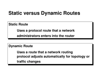
STATIC AND FATIGUE BOLT DESIGN
Thread standards & definition d: major diameter • p: pitch • Fig. 8.1 Terminology of screw threads l: lead • Multiple threads • http://www.gizmology.net/nutsbolts.htm
The thread size is specified by the p for metric sizes. • At is tensile stress area of unthreaded rod. • Geometrical data for Standard Bolts (SI)
Bolt Types Three types of threaded fastener. (a) Bolt and nut; (c) Cap screw; (c) stud.
Bolt strength Bolts in axial loading fail at the: •Fillet under the head. •Thread runout. •1st thread engaged in the nut. Material properties of steel bolts
Tension joints Fi: preload Fb = Pb + Fi . Total force in each bolt Fm = Pm – Fi. Force Carried by the Joint • • • P: external tensile load per bolt • Pb: portion of P taken by bolt • Pm: portion of P taken by members • C: stiffness constant of the joints (joint constant) • ??= ??+ ?? ??= −??+ ?(1 − ? A bolted connection loaded in tension by the forces P
Static load Fi can be determined as: where SPis the proof strength and can be found in tables 8 -11 ???? ?? + ?? ??= Yield factor of safety guarding against exceeding Sp ??= ????− ?? Load factor of safety guarding against overloading ?? ?? Load factor for joint separation ?(1 − ? ?0=
BOLT FAILURE MODES a: tensile failure ???? ?? + ?? ??= ?? ??= ?? ??= ?? ??= ????− ?? ?? ?? b: Joint Separation To separate the joint: Fm 0 ?? ?(1 − ? ?0= ?0=???? ?
Example of bolt under static load An M14x2 grade 5.8 bolt is used in a bolted connection. The joint constant is C = 0.3498. The factors of safety to be applied are 2 against tensile stress failure and 3.5 against joint separation. Calculate the maximum force (P) that can be applied to this unit for reusable application.
Solution. 2 A Sp 115 mm 380 MPa From table 8-1 & 8-11 t ??= 0.75 ???? ?? = 32.775 kN a) Tensile Failure b) Joint separation ?? ??= ????− ?? ?(1 − ? ?0= ?? ? = 15.6 kN ? = 14.4 kN
?? Gasketed joints ???? ?(??????/? + ?? ??= ????− ?? ?(??????/? ???? (1 − ? ?? ??= ???= OR ?? ???=?0(1 − ? ? (??????/? (1 − ? ?0= OR ??? Where: 3 ≤??? ??≤ 6 Nis the no. of bolts ?? is the diameter of the bolt circle ? is 0.75 or 0.9 • • •
Example of bolt under static load (gasket joint) A cylinder of internal diameter 1000mm and wall thickness 3mm is subjected to an internal pressure equivalent to 1.5 MPa. Assume safety factors of 2.5 against bolt tensile failure, 3.5 against joint separation, and class 8.8 bolts in either fine or coarse threads. Design a suitable bolt group for the cylinder head for reusable application and an assumed joint constant of 0.45. Give a suitable bolt pitch circle diameter, ??.
Solution 600 Sp MPa From table 8-1 & 8-11 ???? (1−? ?? = 8836 ??2 ???= ?? can be estimated by calculating the cerconferance of the circle ? = ?? ? for a siutable spacing between bolts,? can be estimated as 36 bolts ??= 245.4 ??2
Solution (cont.) for ? = 36 and??= 245.4 ??2, we can select M20x1.5 from Table 8-1 ??can be estimated as ??=1000 + 2(3)+2(47) = 1100 ??? ?? ?1100 36 ∗ 20= 4.8 NUMBER OF BOLTS = 36 BOLT DESIGNATION : M20 X 1.5 BOLT PITCH CIRCLE DIAMETER = 1100 mm (NOTE: This is only one possible solution)
Dynamic Loading a) Tensile Failure CP max Fi N CP min Fi N iF t Load variation Per Bolt
Dynamic Loading (cont.) a) Tensile Failure The alternating and mean forces per bolt are, respectively, CP CP F F max min P P i i where max min C P N N P a P a 2 a 2 N CP CP F F max min P P i i C P where N N max min P m P F m m i 2 2 N Applying ??to the external load at both equations and substitute in Goodman line and rearranging: S S n C S NA P S P S f ut p S a S ut m e A e t n t f S N S C P S P e ut p a ut m e where ?? & N are the fatigue factor of safety and no.of bolts respectively
Dynamic Loading (cont.) b) Joint Separation 1 ( ) C P max Fi N 1 ( ) C P min Fi N Fm t Load variation Per Bolt
Dynamic Loading (cont.) b) Joint Separation NF 1 i n 2 f 1 ( ) C max P where ??2 is the seperation factor of safety Table 8-17 Material Properties (Endurance Strength) for Standard Bolts (SI)
Example of bolt under dynamic load The fluctuating pressure in the cylinder shown is given by: Using Class 10.9 M24x2 bolts with a factor of safety of 2.5 against bolt tensile failure and 3 against joint separation. determine the number of bolts which should be used for the application. Assume that the bolts carry 25% of the external load. Assume a reusable application. 6 2 p 10 2 ( cos ) t N / m
Solution. ???= 1040 MPa At 2 830 384 mm Sp MPa From table 8-1 & 8-11 From table 8-17 1 * 6 ??= 162 MPa P P max 2 4 2 2 * 1 * 1 6 6 3 3 * 10 N ? = 0.25 10 10 * N P 3 * 10 N ? = 0.75 max max 4 4 1 6 2 2 2 2 * 1 * 10 * 1 6 * 1 * 1 6 6 1 P * P 1 * 10 N P 3 P * min 10 N 4 N N min max min 4 4 P min min 1 * 4 2 2 P P * 1 * 1 1 2 4 2 6 6 P P * 1 max min P max * 1 P 1 * 10 N 10 P a 1 * 2 10 2 N 10 6 6 max a N min P N P * 2 4 4 a 4 2 2 2 P P * 1 P P m P P max * 10 1 10 6 6 2 max min 4 2 P N 2 * 10 N max min max P P P 1 P min * 10 min N P * 1 * 1 m 6 a 6 2 4 2 4 * 2 * N m 2 2 4 2 P P * 1 6 max min P 2 * 10 N m 2 4
Solution (cont.) a) Tensile Failure b) Joint separation 1 ( ) C max P n C P S P S N n f a S ut m e N f S A S A S p t e t ut p 22 1 . 26 Check the bolt spacing with N is 26: ??? ?? ?1160 26 ∗ 24= 5.8 Check the bolt spacing with N is 30: ?1160 30 ∗ 24= 5.06