metal forming process
process of forming


metal forming process
E N D
Presentation Transcript
Metal Forming Processes
Books chapter Fundamentos de Manufactura Moderna: Materiales, Procesos Fundamental of modern manufacturing Materials, Processes and systems
General classification of metal forming processes Metal forming: Large set of manufacturing processes in which the material is deformed plastically to take the shape of the die geometry. The tools used for such deformation are called die, punch etc. depending on the type of process. Plastic deformation: Stresses beyond yield strength of the workpiece material is required. Categories: Bulk metal forming, Sheet metal forming stretching
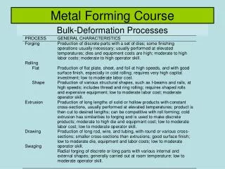
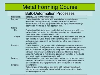
Classification of basic bulk forming processes Bulk forming: It is a severe deformation process resulting in massive shape change. The surface area-to-volume of the work is relatively small. Mostly done in hot working conditions. Forging Rolling Rolling: In this process, the workpiece in the form of slab or plate is compressed between two rotating rolls in the thickness direction, so that the thickness is reduced. The rotating rolls draw the slab into the gap and compresses it. The final product is in the form of sheet. Forging: The workpiece is compressed between two dies containing shaped contours. The die shapes are imparted into the final part.
Classification of basic bulk forming processes Bulk forming: It is a severe deformation process resulting in massive shape change. The surface area-to-volume of the work is relatively small. Mostly done in hot working conditions. Wire drawing Extrusion Extrusion: In this, the workpiece is compressed or pushed into the die opening to take the shape of the die hole as its cross section. Wire or rod drawing: similar to extrusion, except that the workpiece is pulled through the die opening to take the cross-section.
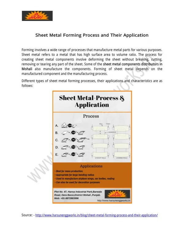
Classification of basic sheet forming processes Sheet forming: Sheet metal forming involves forming and cutting operations performed on metal sheets, strips, and coils. The surface area-to-volume ratio of the starting metal is relatively high. Tools include punch, die that are used to deform the sheets. Deep drawing Bending Bending: In this, the sheet material is strained by punch to give a bend shape (angle shape) usually in a straight axis. Deep (or cup) drawing: In this operation, forming of a flat metal sheet into a hollow or concave shape like a cup, is performed by stretching the metal in some regions. A blank-holder is used to clamp the blank on the die, while the punch pushes into the sheet metal. The sheet is drawn into the die hole taking the shape of the cavity.
Classification of basic sheet forming processes Sheet forming: Sheet metal forming involves forming and cutting operations performed on metal sheets, strips, and coils. The surface area-to-volume ratio of the starting metal is relatively high. Tools include punch, die that are used to deform the sheets. shearing Shearing: This is nothing but cutting of sheets by shearing action.
Cold working, warm working, hot working Cold working: Generally done at room temperature or slightly above RT. Advantages compared to hot forming: (1) closer tolerances can be achieved; (2) good surface finish; (3) because of strain hardening, higher strength and hardness is seen in part; (4) grain flow during deformation provides the opportunity for desirable directional properties; (5) since no heating of the work is involved, furnace, fuel, electricity costs are minimized, (6) Machining requirements are minimum resulting in possibility of near net shaped forming. Disadvantages: (1) higher forces and power are required; (2) strain hardening of the work metal limit the amount of forming that can be done, (3) sometimes cold forming- annealing-cold forming cycle should be followed, (4) the work piece is not ductile enough to be cold worked. Warm working: In this case, forming is performed at temperatures just above room temperature but below the recrystallization temperature. The working temperature is taken to be 0.3 Tmwhere Tmis the melting point of the workpiece. Advantages: (1) enhanced plastic deformation properties, (2) lower forces required, (3) intricate work geometries possible, (4) annealing stages can be reduced.
Cold working, warm working, hot working Hot working: Involves deformation above recrystallization temperature, between 0.5Tm to0.75Tm. Advantages: (1) significant plastic deformation can be given to the sample, (2) significant change in workpiece shape, (3) lower forces are required,(4) materials with premature failure can be hot formed, (5) absence of strengthening due to work hardening. Disadvantages: (1) shorter tool life, (2) poor surface finish, (3)lower dimensional accuracy, (4) sample surface oxidation
Bulk forming processes Forging • It is a deformation process in which the work piece is compressed between two dies, using either impact load or hydraulic load (or gradual load) to deform it. •It is used to make a variety of high-strength components for automotive, aerospace, and other applications. The components include engine crankshafts, connecting rods, gears, aircraft structural components, jet engine turbine parts etc. • Category based on temperature : cold, warm, hot forging • Category based on presses: impact load => forging hammer; gradual pressure => forging press • Category based on type of forming: Open die forging, impression die forging, flashless forging Open die forging In open die forging, the work piece is compressed between two flat platens or dies, thus allowing the metal to flow without any restriction in the sideward direction relative to the die surfaces.
Bulk forming processes flashless forging impression die forging In impression die forging, the die surfaces contain a shape that is given to the work piece during compression, thus restricting the metal flow significantly. There is some extra deformed material outside the die impression which is called as flash. This will be trimmed off later. In flashless forging, the work piece is fully restricted within the die and no flash is produced. The amount of initial work piece used must be controlled accurately so that it matches the volume of the die cavity.
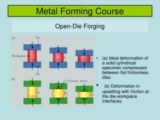
Open die forging A simplest example of open die forging is compression of billet between two flat die halves which is like compression test. This also known as upsetting or upset forging. Basically height decreases and diameter increases. Under ideal conditions, where there is no friction between the billet and die surfaces, homogeneous deformation occurs. In this, the diameter increases uniformly throughout its height. In ideal condition, ε = ln (ho/h). h will be equal to hf at the end of compression, ε will be maximum for the whole forming. Also F = σf A is used to find the force required for forging, where σf is the flow stress corresponding to ε at that stage of forming. Start of compression Partial compression Completed compression
Open die forging In actual forging operation, the deformation will not be homogeneous as bulging occurs because of the presence of friction at the die-billetinterface. This friction opposes the movement of billet at the surface. This is called barreling effect. The barreling effect will be significant as the diameter-to-height (D/h) ratioof the workpart increases, due to the greater contact area at the billet–die interface. Temperature will also affect the barrelingphenomenon. Completed compression Partial compression Start of compression In actual forging, the accurate force evaluation is done by using, F = Kf σf A by considering the effect of friction and D/h ratio. Here, K =1+0.4D f h Where Kf = forging shape factor, μ = coefficient of friction, D = work piece diameter, h = work piece height
Open die forging Typical load-stroke curve in open die forging Effect of D/h ratio on load: CompressionLoad µ2 > µ1 µ2 µ1 µ0 D/h Effect of h/D ratio on barreling: Cylinder having h/D < 2 with friction Long cylinder: h/D >2 Frictionless compression
Closed die forging Closed die forging called as impression die forging is performed in dies which has the impression that will be imparted to the work piece through forming. In the intermediate stage, the initial billet deforms partially giving a bulged shape. During the die full closure, impression is fully filled with deformed billet and further moves out of the impression to form flash. In multi stage operation, separate die cavities are required for shape change. In the initial stages, uniform distribution of properties and microstructure are seen. In the final stage, actual shape modification is observed. When drop forging is used, several blows of the hammer may be required for each step. Startingstage Final stagewith flashformation Intermediate stage
Closed die forging The formula used for open die forging earlier can be used for closeddie forging, i.e., F = Kf σfA Where F is maximum force in the operation; A is projected area of thepart including flash, σfis flow stress of the material, Kfis forging shape factor. Now selecting the proper value of flow stress is difficult because the strain varies throughout the work piece for complex shapes and hence the strength varies. Sometimes an average strength is used. Kf is used for taking care of different shapes of parts. Table shows the typical values ofKf used for force calculation. In hot working, appropriate flow stress at that temperature is used. The above equation is applied to find the maximum force during the operation, since this is the load that will determine the required capacityof the press used in the forging operation.
Closed die forging Impression die forging is not capable of making close tolerance objects. Machining is generally required to achieve the accuracies needed. The basic geometry of the part is obtained from the forging process, with subsequent machining done on those portions of the part that require precision finishing like holes, threads etc. In order to improve the efficiency of closed die forging, precision forging was developed that can produce forgings with thin sections, more complex geometries, closer tolerances, and elimination of machining allowances. In precision forging operations, sometimes machining is fully eliminated which is called near-net shape forging.
Flashless forging The three stages of flashless forging is shown below: In flashless forging, most important is that the work piece volumemust equal the space in the die cavity within a very closetolerance. If the starting billet size is too large, excessive pressures will causedamage to the die and press. If the billet size is too small, the cavity will not befilled. Because of the demands, this process is suitable to make simple and symmetrical part geometries, and to work materials such as Al, Mg andtheir alloys.
Flashless forging Coining is a simple application of closed die forging in which fine details in the die impression are impressed into the top or/and bottom surfaces of the work piece. Though there is little flow of metal in coining, the pressures required to reproduce the surface details in the die cavity are at par with otherimpression forging operations. Starting ofcycle Fully compressed Ram pressure removed and ejection of part Making of a coin
Forging hammers, presses and dies Hammers: Hammers operate by applying an impact loading on the work piece. This is also called as drop hammer, owing to the means of delivering impactenergy. When the upper die strikes the work piece,the impact energy applied causes the part to take the form of the die cavity. Sometimes, several blows of the hammer are required to achieve the desired change in shape. Drop hammers are classifiedas: Gravity drop hammers, power drophammers. Gravity drop hammers - achieve their energy by the falling weight of a heavy ram. Theforce of the blow is dependent on the height of the drop and the weight of theram. Drop hammers Power drop hammers - accelerate the ramby pressurized air orsteam.
Forging hammers, presses and dies Presses: The force is given to the forging billet gradually, and not like impact force. Mechanical presses: In these presses, the rotating motion of a drive motor is converted into the translation motion of the ram. They operate bymeans of eccentrics, cranks, or knuckle joints. Mechanical presses typically achieve very high forces at the bottom of the forgingstroke. Hydraulic presses : hydraulically driven piston is used to actuate the ram. Screw presses : apply force by a screw mechanism that drives thevertical ram. Both screw drive and hydraulic drive operate at relatively low ram speeds. Forging dies:
Forging hammers, presses and dies Parting line: The parting line divides the upper die from the lower die. In other words, it is the plane where the two die halves meet. The selection of parting line affects grain flow in the part, required load, and flashformation. Draft: It is the amount of taper given on the sides of the part requiredto remove it from the die. Draft angles: It is meant for easy removal of part after operation iscompleted. 3° for Al and Mg parts; 5° to 7° for steelparts. Webs and ribs: They are thin portions of the forging that is parallel and perpendicular to the parting line. More difficulty is witnessed in formingthe part as they becomethinner. Fillet and corner radii: Small radii limits the metal flow and increasestresses on die surfaces during forging. Flash: The pressure build up because of flash formation is controlledproper design of gutter and flash land.
Other forging operations Upset forging: It is a deformation operation in which a cylindrical work piece is increased in diameter with reduction in length. In industry practice, it is done as closed die forging. Upset forging is widely used in the fastener industries to form heads on nails, bolts, and similar products. Feeding of work piece Gripping of work piece and retracting of stop Forward movement of punch and upsetting Forging operation completes
Other forging operations Heading: The following figure shows variety of heading operations with differentdie profiles. Heading a die using open dieforging Round head formed by punchonly Head formed inside dieonly Bolt head formed byboth die and punch Long bar stock (work piece) is fed into the machines by horizontal slides, the end of the stock is upset forged, and the piece is cut to appropriate length to make the desired product. The maximum length that can be upset in a single blow is three times the diameter of the initial wire stock.
Other forging operations Swaging: Swaging is used to reduce the diameter of a tube or a rod at the end of the work piece to create a tapered section. In general, this process is conducted by means of rotating dies that hammer a workpiece in radial direction inward to taper it as the piece is fed into the dies. A mandrel is required to control the shape and size of the internal diameter of tubular parts duringswaging. Swaging Radial forging: This operation is same as swaging, except that in radial forging, the dies do not rotate around the work piece, instead, the work is rotated as it feeds into the hammering dies. Diameter reduction of solid work Tube tapering Swaging to form a groove on the tube Swaging with different die profiles Swaging the edge of a cylinder
Other forging operations Roll forging: It is a forming process used to reduce the cross section of a cylindrical or rectangular rod by passing it through a set of opposing rolls that havematching grooves w.r.t. the desired shape of the final part. It combines both rolling and forging, but classified as forgingoperation. Depending on the amount of deformation, the rolls rotate partially. Roll-forged parts are generally stronger and possess desired grain structure compared to machining that might be used to produce the samepart.
Other forging operations Orbital forging: In this process, forming is imparted to the workpiece by means of a cone- shaped upper die that is simultaneously rolled and pressed into the work. The work is supported on a lower die. Because of the inclined axis of cone, only a small area of the work surfaceis compressed at any stage of forming. As the upper die revolves, the area under compression also revolves. Because of partial deformation contact at any stage of forming, there is a substantial reduction in press load requirement.
Other forging operations Isothermal forging: It is a hot-forging operation in which the work is maintained at some elevated temperature during forming. The forging dies are alsomaintained at the same elevated temperature. By avoiding chill of the work in contact with the cold die surfaces, the metal flows more readily and the force requirement is reduced. The process is expensive than conventional forging and is usually meantfor difficult-to-forge metals, like Ti, superalloys, and for complex partshapes. The process is done in vacuum or inert atmosphere to avoid rapidoxidation of the die material.
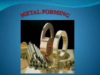
Extrusion Extrusion is a bulk forming process in which the work metal is forced or compressed to flow through a die hole to produce a desiredcross-sectional shape. Example: squeezing toothpaste from a toothpastetube. Advantages : - Variety of shapes are possible, especially using hotextrusion - Grain structure and strength properties are enhanced in cold andwarm extrusion - Close tolerances are possible, mainly in cold extrusion Types of extrusion: Direct or forward extrusion, Indirect or backwardextrusion Direct extrusion: - A metal billet is first loaded into a container having die holes.Aram compresses the material, forcing it to flow through the die holes. -Some extra portion of the billet will be present at the end of the processthat cannot be extruded and is called butt. It is separated from the product by cutting it just beyond the exit of the die.
Extrusion Metal forced/squeezed out through a hole (die) Typical use: ductile metals (Cu, Steel, Al, Mg), Plastics, Rubbers Common products: Al frames of white-boards, doors, windows, …
Extrusion Direct extrusion -In direct extrusion, a significant amount of friction exists between the billet surface and the container walls, as the billet is forced to slide toward the die opening. Because of the presence of friction, a substantial increase in theram force is required. -In hot direct extrusion, the friction problem is increased by the presence of oxide layer on the surface of the billet. This oxide layer can cause defects in the extruded product. -In order to address these problems, a dummy block is used between the ram and the work billet. The diameter of the dummy block is kept slightly smaller than the billet diameter, so that a thin layer of billet containing the oxide layeris left in the container, leaving the final product free ofoxides.
Extrusion Making hollow shapes using direct extrusion Hollow sections like tubes can be made using direct extrusion setup shownin above figure. The starting billet is prepared with a hole parallel to its axis. As the billet is compressed, the material will flow through the gap between the mandrel and the die opening. Indirect extrusion: - In this type, the die is mounted to the ram and not on the container. As the ram compresses the metal, it flows through the die hole on the ram side which is in opposite direction to the movement ofram. -Since there is no relative motion between the billet and the container, thereis no friction at the interface, and hence the ram force is lower than in direct extrusion. - Limitations: lower rigidity of the hollow ram, difficulty in supportingthe extruded product at theexit
Extrusion Indirect extrusion: solid billet and hollow billet Simple analysis of extrusion Pressure distribution and billet dimensions in direct extrusion
Extrusion Assuming the initial billet and extrudate are in round cross-section.An important parameter, extrusion ratio (re), is defined asbelow: A A0 - CSA of the initialbillet Af - CSA of the extrudedsection r = 0 e A f True strain in extrusion under ideal deformation (no friction andredundant work) is given by, A = ln(r ) = ln(A ) 0 e f Under ideal deformation, the ram pressure required to extrude thebillet through die hole is given by, A p = Yf ln(re ) = Yfln( where Y = Note: The average flow stress is foundout by integrating the flow curve equation between zero and the final straindefining the range offorming Kn ) 0 f 1+n fA Where Yf is average flow stress, and is maximum strain value during the extrusion process. The actual pressure for extrusion will be greater than in ideal case,because of the friction between billet and die and billet and containerwall.
Extrusion There are various equations used to evaluate the actual true strain and associated ram pressure during extrusion. The following relationproposed by Johnson is of greatinterest. x= a+blnre= a+b p =Yfx Where angle. Typical values are: a = 0.8, b = 1.2 -1.5. x is extrusion strain; a and b are empirical constants for a givendie In direct extrusion, assuming that friction exists at the interface, we canfind the actual extrusion pressure as follows: billet-container friction force = additional ram force to overcomethat friction p D 2 Where pf is additional pressure required to overcome friction, p is pressure against the container wall peD0 L = 0 f e 4 The above eqn. assume sliding friction condition. Assuming sticking friction at the interface, we can write: pf D02 KD0L = Where K is shear yield strength & m = 1 4
Extrusion =4KL D The above eqn. gives, pf 0 2L K =Yf Assuming, we get, p =Y f f D 2 0 This is the additional pressure requiredto overcome friction duringextrusion. Now the actual ram pressure required for direct extrusion is given by, The shape of the initial pressure buildup depends on die angle. Higher die angles cause steeper pressurebuildups. L is the billet length remaining to be extruded, and D0 is the initial diameter of the billet. Here p is reduced as the remaining billet length decreases during the extrusion process. Ram pressure variation with stroke fordirect and indirect extrusion is shown in Figure.
Empirical formulae for extrusion pressure Hot extrusion of Al alloys: For extrusion of pure Al, Al-Zn alloy, Al-Zn-Mg alloy in the temperature range of 50- 500°C. Here R = 1/(1-r) where ‘r’ is the relative reduction in area pe /0 = 0.52+1.32lnR for values of R from 1 to 100 pe/0= −13+ 4.78ln R for values of R from 100 to 1000 Cold extrusion of steel: A1 − A2 N p =0.262F(A )0.787(2)0.375 e 100 Where A = percent reduction in area = 1A r r 2 mm F =Yield strength of steel Yield strength of lead
Extrusion dies - Two important factors in an extrusion die are: die angle, orificeshape. -For low die angles, surface area of the die is large, resulting inincreased friction at the die-billet interface. Higher friction results in higher ramforce. - For a large die angle, more turbulence in the metal flow is causedduring reduction, increasing the ram forcerequired. -The effect of die angle on ram force is a U-shaped function, shown in Figure. So, an optimum die angle exists. The optimum angle dependson various factors like work material, billet temperature, andlubrication. effect of die angle on ram force Definition of die angle in direct extrusion
Extrusion dies - The extrusion pressure eqns. derived earlier are for a circular dieorifice. -The shape of the die orifice affects the ram pressure required to performan extrusion operation, as it determines the amount of squeezing of metalbillet. -The effect of the die orifice shape can be assessed by the die shapefactor, defined as the ratio of the pressure required to extrude a cross section of a given shape relative to the extrusion pressure for a circular cross section of the same area. Where kx is the die shape factor in extrusion; Cx is the perimeter of the extruded cross section, and Cc is the perimeter of a circle of the same area as the actual extruded shape. cx varies from 1 to6. cc
Die materials For hot extrusion - tool and alloy steels. Important properties of die materials are high wear resistance, highthermal conductivity to remove heat from theprocess. For cold extrusion - tool steels and cementedcarbides. Carbides are used when high production rates, long die life, andgood dimensional control are expected.
Other extrusion processes Impact extrusion: -It is performed at higher speeds and shorter strokes. The billet isextruded through the die by impact pressure and not just by applyingpressure. -But impacting can be carried out as forward extrusion, backwardextrusion, or combination of these. Backward extrusion forward extrusion combinedextrusion R. Ganesh Narayanan,IITG
Other extrusion processes - Impact extrusion is carried out as cold forming. Very thin walls arepossible by backward impact extrusion method. Eg: making tooth paste tubes, battery cases. - Advantages of IE: large reductions and high productionrates Hydrostatic extrusion: Hydrostatic extrusion
Other extrusion processes In hydrostatic extrusion, the billet is surrounded with fluid insidethe container and the fluid is pressurized by the forward motion of theram. There is no friction inside the container because of the fluid, and frictionis minimized at the die opening. If used at high temperatures, special fluids and procedures must be followed. Hydrostatic pressure on the work and no friction situation increases the material’s ductility. Hence this process can be used on metals thatwould be too brittle for conventional extrusion methods. This process is also applicable for ductile metals, and here highreduction ratios are possible. The preparation of starting work billet is important. The billet must be formed with a taper at one end to fit tightly into the die entry angle, sothat it acts as a seal to prevent fluid leakage through die hole underpressure.
Defects during extrusion Centerburst: -This is an internal crack that develops as a result of tensile stresses along the center axis of the workpiece during extrusion. A large material motion at the outer regions pulls the material along the center of the work. Beyond a critical limit, bursting occurs. -Conditions that promote this defect are: higher die angles, low extrusion ratios, and impurities in the work metal. This is also called as Chevron cracking. Centerburst Piping: It is the formation of a sink hole in the end of the billet. This is minimized by the usage of a dummy block whose diameter is slightly less than that of the billet. Piping Surface cracking: This defect results from high workpiece temperatures that cause cracks to develop at the surface. They also occur at higher extrusion speeds, leading to high strain rates and heat generation. Higher friction at the surface and surface chilling of high temperature billets in hot extrusion also cause this defect. Surfacecracking
Wire, rod, bar drawing - In this bulk forming process, a wire, rod, bar are pulled through a diehole reducing their cross-section area. Wire, rod, bar drawing Difference between wire drawing and roddrawing: Initial stock size: - The basic difference between bar drawing and wire drawing is the stocksize that is used for forming. Bar drawing is meant for large diameter bar and rod, while wire drawing is meant for small diameter stock. Wire sizes of the order of 0.03 mm are produced in wiredrawing.
Wire, rod, bardrawing Operating stages: -Bar drawing is generally done as a single stage operation, in which stock is pulled through one die opening. The inlet bars are straight and not inthe form of coil, which limits the length of the work that can be drawn. This necessitates a batch type operation. -In contrast, wire is drawn from coils consisting of several hundredmeters of wire and is drawn through a series of dies. The number of dies varies between 4 and 12. This is termed as ‘continuous drawing’ because of the long production runs that are achieved with the wire coils. The segments can be butt-welded to the next to make the operation trulycontinuous.
Simple analysis of wire drawing True strain in wire drawing under ideal deformation (no friction and redundant work) is given by, 1 1−r = ln( A0 ) = ln( ) Here r = (A0 – Af) /A0 f A Under ideal deformation, the stress required in wire drawing is given by, Kn =Y ln( A0) ,Yf is the average flow stress Here Yf =1+ n d f Af corresponding to ε mentioned in above equation. In order to consider the effect of die angle and friction coefficient on the drawing stress, Schey has proposed another equation as shown below:
Simple analysis of wire drawing Here is a term that accounts for inhomogeneous deformation which is found by the following eqn. for round cross-section. = 0.88 +0.12 D Here D is the average diameter of the workpiece, LC is the contact length of the work with die given by, Lc + Df =D0 − Df D =D0 ;L 2sin C 2 Finally the drawing force is given by, F = Afσd The power required for drawing is given by multiplying drawing force with exit velocity of the workpiece Wire is drawn through a draw die with entrance angle 15°. Starting diameter is 2.5 mm and final diameter 2 mm. The coefficient of friction at the work–die interface is 0.07. The metal has a strength coefficient K = 205 MPa and a strain-hardening exponent n = 0.2. Determine the draw stress and draw force in this operation.
Maximum reduction per pass Increase in reduction, increase the draw stress. If the reduction is large enough, draw stress will exceed the yield strength of the material. Then the wire will just elongate rather than new material being drawn into the die hole. To have a successful wire drawing operation, drawing stress should be less than yield strength of the drawnmetal. Assume a perfectly plastic material (n = 0), no friction and redundantwork, then, A A d =Yfln( 1 0 ) =Y ln( 0 ) = Yln( ) =Y 1−r Af Af which means that 1 A Af 0 )= ln( ) =1 ln( 1−r This gives a condition that the maximum possible reduction, rmaxis rmax = 0.632 (theoretical maximumlimit) This analysis ignores the effects of friction and redundant work, which would further reduce the maximum value, and strain hardening, which would increase the maximum reduction because of the stronger wire than the starting metal. Reductions of 0.5-0.3 per pass seem to be possible in industrial operations.
Wire drawing equipment Continuous drawing of wire Drawing bar by draw bench