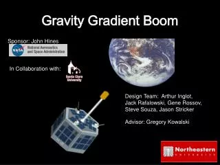
Gravity Gradient Boom
Gravity Gradient Boom. Sponsor: John Hines. In Collaboration with:. Design Team: Arthur Inglot, Jack Rafalowski, Gene Rossov, Steve Souza, Jason Stricker. Advisor: Gregory Kowalski. What is a Gravity Gradient Boom. Boom Arm. Tip Mass. Satellite. Retracted. Deployed. Boom Stowed.

Gravity Gradient Boom
E N D
Presentation Transcript
Gravity Gradient Boom Sponsor: John Hines In Collaboration with: Design Team: Arthur Inglot, Jack Rafalowski, Gene Rossov, Steve Souza, Jason Stricker Advisor: Gregory Kowalski
What is a Gravity Gradient Boom Boom Arm Tip Mass Satellite Retracted Deployed
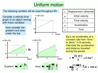
Satellite stabilization and control Purpose: Maintain communication link to satellites antennas Maintain a desired view for imaging Heat dissipation and distribution Three Axes Location Direction Attitude Control
Problem Statement • Design and develop a Gravity GradientBoom as a stand alone Passive Attitude Control for a small satellite, conforming to the requirements put forth by NASA.
ONYX • Project developed by Santa Clara U (Ca) • Collaboration with NASA, AFOSR and DARPA and part of the University Nanosatellite Program • Onboard autonomy experiment • Purpose: • To monitor anomalies in orbital motion and resolve them using two independent processing systems autonomously while observing Earth. • Image capturing in multiple spectrums • Research tool and educational service for K-12 and college students.
ONYX • 30kg • 21cm/hexagonal sides x 42cm tall • Center of gravity location [X, Y, Z]: [-0.326, 15.5, -0.170] cm • Moment of inertia about CG: XX: 5.3E6g*cm2 • YY: 4.6E6g*cm2 • ZZ: 5.0E6g*cm2
Requirements and Constraints Orientation requirements: +/- 5 degrees • Constraints: • Mass: <10 kg • Volume/Dimensions: 12 x 12 x 15 cm (.00216m3 ) • Power: <30 watts • Opening on top: 10 cm x 10 cm • Preliminary Damping: Provided • Shock Resistance: ±20 Gs • Min. Resonance Freq.: 500 Hz
Newton’s Law of Universal Gravitation Low Earth Orbit is 200km-2000km Mass of Earth is 5.9742 x 1024kg Radius of Earth is 6380 km G is the universal constant, 6.67 x 10⁻¹¹Nm2/kg2
Coilable Boom Very light weight (< 50g/m) Stowage size is very small Low cost High Reliability Deployment Options • Telescoping Booms • High torsion and bending strength • Intended for many cycles • Extreme deployment and retraction force • Tethers • Complicated and costly • Motor unwinds long lengths of tether material (2 Km) • Oscillation and reliability concerns • Prone to space collisions
Wire Drum Deployer • Copper-Beryllium Wire wound on a drum • Proven Technology with industry backing • Copper-Beryllium provides sufficient tension • Can be deployed using an electric motor or a passive spring assembly • Low weight, low cost, and space saving packaging • Due to low weight of overall wire deployer a heavier tip mass may be used to provide more stabilization • Have to account for physical and thermal oscillations, additional hardware such as dampers may have to be implemented
Wire Deployment System Tungsten Alloy Tip Mass Deployment Spider Delrin Mounting Ring Frangibolt ® system Copper Beryllium Wire Spool Aluminum 6061 Machined Components Release Solenoid Stowed Configuration Deployed Configuration
The Frangibolt ® System • Non-Explosive Actuator • High Factor of safety • Consumes 25 Watts • Yield strength 2200 N • Compact size • Flight certified with space heritage
Wire Deployer Mounted Deployed
Cosmos Deformation Analysis 6.295E6 N/m2 6.295E6 N/m2
Final Optimized Decisions for MATLAB Input • Length of wire:20.0 m • Tip Mass:3.00 kg • Orbit:Circular • Altitude:500km • Inputing the parameters into the MATLAB program created from ONYX’s data show resulted for stabilization.
Stabilization Graph Settling Time:9.25 days from 30o +/- 5o tolerance
Gravity Gradient Boom must overcome all disturbance torques in space Proper Stabilization
Final Optimized Constraints • System Mass of 3.76kg, (6.24kg Under Max) • Center of Mass and Moment of Inertia do not hinder physical properties of the ONYX • High degree of accuracy with initial accuracy of 5 degrees stabilizing to as low as 2 degrees • Low Estimated cost of $4,000 • Highly adaptable to other satellites of similar size
Improvements • Improve modeling for FEA Vibration analysis • Improve metal on metal contact • Integrate the use of a DC motor for more control