Download
1 / 56
560 likes | 1.02k Views
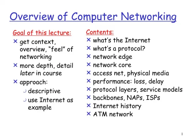
Goal of this lecture: get context, overview, “feel” of networking more depth, detail later in course approach: descriptive use Internet as example. Contents: what’s the Internet what’s a protocol? network edge network core access net, physical media performance: loss, delay

E N D
Goal of this lecture: get context, overview, “feel” of networking more depth, detail later in course approach: descriptive use Internet as example Contents: what’s the Internet what’s a protocol? network edge network core access net, physical media performance: loss, delay protocol layers, service models backbones, NAPs, ISPs Internet history ATM network Overview of Computer Networking
millions of connected computing devices: hosts, end-systems pc’s workstations, servers PDA’s phones, toasters running network apps communication links fiber, copper, radio, satellite routers: forward packets (chunks) of data thru network router workstation server mobile local ISP regional ISP enterprise network What’s the Internet: “nuts and bolts” view
protocols: control sending, receiving of msgs e.g., TCP, IP, HTTP, FTP Internet: “network of networks” loosely hierarchical public Internet versus private intranet Internet standards RFC: Request for Comments IETF: Internet Engineering Task Force What’s the Internet: “nuts and bolts” view router workstation server mobile local ISP regional ISP enterprise network
communication infrastructure enables distributed applications: WWW, email, games, e-commerce, database., voting What else? communication services provided: connectionless connection-oriented cyberspace [Gibson]: “a consensual hallucination experienced daily by billions of operators, in every nation, ...." What’s the Internet: a service view
Internet Engineering Task Force (IETF) http://www.ietf.org World Wide Web Consortium (W3C) http://www.w3c.org Association for Computing Machinery (ACM) http://www.acm.org ”Special interest group in Data Communications” Institute of Electrical and Electronics Engineers (IEEE) http://www.comsoc.org ”Communications Society” http://www.computer.org/ ”Computer Society” Connected: An Internet Encyclopedia http://www.FreeSoft.org/CIE/index.htm Some useful Web sites
human protocols: “hello” – “hello” “could you tell me the time please?” … specific msgs sent … specific actions taken when msgs received, or other events network protocols: For machines rather than humans all communication activities in Internet governed by protocols protocols define msg format, order of msgs sent and received among network entities, and actions taken on msg transmission & receipt What’s a Protocol?
a human protocol and a computer network protocol: Hi TCP connection req. Hi TCP connection reply. Get http://dpnm.postech.ac.kr/cs702/index.html 2:00 <file> Could you tell me what time it is? time What’s a protocol?
network edge: applications and hosts network core: routers network of networks access networks, physical media: communication links A closer look at network structure:
end systems (hosts): run application programs e.g., WWW, email at “edge of network” client/server model client host requests, receives service from server e.g., WWW client (browser)/ server; email client/server peer-peer model: host interaction symmetric e.g.: teleconferencing, P2P apps (e.g., Morpheus) The network edge:
Goal: data transfer between end systems handshaking: setup (prepare for) data transfer ahead of time Hello, hello back human protocol set up “state” in two communicating hosts TCP - Transmission Control Protocol Internet’s connection-oriented service TCP [RFC 793] reliable, in-order byte-stream data transfer loss: acknowledgements and retransmissions flow control: sender won’t overwhelm receiver congestion control: senders “slow down sending rate” when network congested Network edge: connection-oriented service
Goal: data transfer between end systems UDP - User Datagram Protocol [RFC 768]: Internet’s connectionless service unreliable data transfer no flow control no congestion control App’s using TCP: HTTP (WWW), FTP (file transfer), Telnet (remote login), SMTP (email) App’s using UDP: streaming media, teleconferencing, Internet telephony Network edge: connectionless service
mesh of interconnected routers the fundamental question: how is data transferred through the network? Circuit switching: dedicated circuit per call: telephone net Packet switching: data sent thru net in discrete “chunks” The Network Core
End-to-end resources reserved for “call” link bandwidth, switch capacity dedicated resources: no sharing circuit-like (guaranteed) performance call setup required Network Core: Circuit Switching
network resources (e.g., bandwidth) divided into “pieces” pieces allocated to calls resource piece idle if not used by owning call (no sharing) dividing link bandwidth into “pieces” frequency division time division Network Core: Circuit Switching
Assumptions: A sent file to B: 640Kbits All links use TDM with: 24 slots bit rate of 1.536 Mbps Establishing end-end circuit: 500 msec How long does it take to send the file? Circuit Switching: A numerical example
Each end-to-end data stream divided into packets user A, B packets share network resources each packet uses full link bandwidth resources used as needed, Bandwidth division into “pieces” Dedicated allocation Resource reservation Network Core: Packet Switching Resource contention: • aggregate resource demand can exceed amount available • congestion: packets queue, wait for link use • store and forward: packets move one hop at a time • transmit over link • wait turn at next link
D E Network Core: Packet Switching 10 Mbps Ethernet C A statistical multiplexing 1.5 Mbps B queue of packets waiting for output link 45 Mbps
Packet-switching: store and forward behavior Network Core: Packet Switching
1 Mbit link each user: 100Kbps when “active” active 10% of time circuit-switching: 10 users packet switching: with 35 users, probability > 10 active less than 0.4% Packet switching allows more users to use network! Packet switching versus circuit switching N users 1 Mbps link
Great for bursty data resource sharing no call setup Excessive congestion: packet delay and loss protocols needed for reliable data transfer, congestion control Q: How to provide circuit-like behavior? bandwidth guarantees needed for audio/video apps still an unsolved problem Is packet switching a “slam dunk winner?” Packet switching versus circuit switching
Goal: move packets among routers from source to destination datagram network: destination address determines next hop routes may change during session analogy: driving, asking directions virtual circuit network: each packet carries tag (virtual circuit ID), tag determines next hop fixed path determined at call setup time, remains fixed thru call routers maintain per-call state Packet-switched networks: routing
Circuit-switched networks Packet-switched networks FDM TDM Networks with VCs Datagram Networks connection- oriented connection-oriented & connectionless Network Taxonomy Telecommunication networks
Q: How to connect end systems to edge router? residential access nets institutional access networks (school, company) mobile access networks Keep in mind: bandwidth (bits per second) of access network? shared or dedicated? Access networks and physical media
Dialup via modem up to 56Kbps direct access to router (conceptually) ISDN: integrated services digital network: 128Kbps all-digital connect to router ADSL: asymmetric digital subscriber line up to 1 Mbps home-to-router up to 8 Mbps router-to-home deployment: available via telephone companies, e.g., KT Megapass, Hanaro Hanafos Residential access: point to point access
HFC: hybrid fiber coax asymmetric: up to 10Mbps upstream, 1 Mbps downstream network of cable and fiber attaches homes to ISP router shared access to router among home issues: congestion, dimensioning deployment: available via cable companies, e.g., Thrunet Residential access: cable modems
company/univ local area network (LAN) connects end system to edge router Ethernet: shared or dedicated cable connects end system and router 10 Mbs, 100Mbps, Gigabit Ethernet deployment: institutions, home LANs soon Institutional access: local area networks
shared wireless access network connects end system to router wireless LANs: radio spectrum replaces wire e.g., Netgear 10/54 Mbps wider-area wireless access CDPD (Cellular Digital Packet Data): wireless access to ISP router via cellular network Portable Internet – being stanardardized router base station mobile hosts Wireless access networks
physical link: transmitted data bit propagates across link guided media: signals propagate in solid media: copper, fiber unguided media: signals propagate freely, e.g., radio Twisted Pair (TP) two insulated copper wires Category 3: traditional phone wires, 10 Mbps ethernet Category 5 TP: 100/1000 Mbps Ethernet Physical Media
Coaxial cable: wire (signal carrier) within a wire (shield) baseband: single channel on cable broadband: multiple channel on cable bidirectional common use in 10Mbps Ethernet Physical Media: coax, fiber Fiber optic cable: • glass fiber carrying light pulses • high-speed operation: • 100/1000Mbps Ethernet • high-speed point-to-point transmission (e.g., tens or hundreds of Gbps) • low error rate
signal carried in electromagnetic spectrum no physical “wire” bidirectional propagation environment effects: reflection obstruction by objects interference Physical media: radio Radio link types: • microwave • e.g. up to 45 Mbps channels • LAN (e.g., waveLAN) • 2Mbps, 11Mbps • wide-area (e.g., cellular) • e.g. CDPD, 10’s Kbps • satellite • Bandwidth in the Gbps range • 250 msec end-end delay -two ways
packets experience delay on end-to-end path four sources of delay at each hop nodal processing: check bit errors determine output link queueing time waiting at output link for transmission depends on congestion level of router transmission A propagation B nodal processing queueing Delay in packet-switched networks
Transmission delay: R=link bandwidth (bps) L=packet length (bits) time to send bits into link = L/R Propagation delay: d = length of physical link s = propagation speed in medium (~2x10⁸ m/sec) propagation delay = d/s transmission A propagation B nodal processing queueing Delay in packet-switched networks Note: s and R are very different quantitites!
R=link bandwidth (bps) L=packet length (bits) A=average packet arrival rate Queueing delay traffic intensity = LA/R • LA/R ~ 0: average queueing delay small • LA/R -> 1: delays become large • LA/R > 1: more “work” arriving than can be serviced, average delay infinite!
Networks are complex! many “pieces”: hosts routers links of various media applications protocols hardware, software Question: Is there any hope of organizing structure of network? Or at least our discussion of networks? Protocol “Layers”
ticket (complain) baggage (claim) gates (unload) runway landing airplane routing ticket (purchase) baggage (check) gates (load) runway takeoff airplane routing airplane routing Organization of air travel • a series of steps
ticket (complain) baggage (claim) gates (unload) runway landing airplane routing ticket (purchase) baggage (check) gates (load) runway takeoff airplane routing airplane routing Organization of air travel: a different view Layers: each layer implements a service • via its own internal-layer actions • relying on services provided by layer below
Layered air travel: services Counter-to-counter delivery of person+bags baggage-check-to-baggage-claim delivery people transfer: loading gate to arrival gate runway-to-runway delivery of plane airplane routing from source to destination
airplane routing airplane routing airplane routing Distributed implementation of layer functionality ticket (complain) baggage (claim) gates (unload) runway landing airplane routing ticket (purchase) baggage (check) gates (load) runway takeoff airplane routing arriving airport Departing airport intermediate air traffic sites
Let’s talk about Network Protocols • Organized into layers to reduce complexity • Each protocol belongs to a layer “n” • Layer n protocol is distributed among end systems and packet switches communicating by exchanging messages “n-PDU” • Put together, the protocols of various layers are called “protocol stack” HOST A HOST B n-PDU Layer n Layer n Layer n Layer n n-PDU n-PDU (n-1)-PDU Layer n Layer n Layer n-1 Layer n-1 • Layer n is said to rely on layer n-1 to deliver its n-PDUs • Layer n-1 is said to offer “services” to layer n, e.g., guaranteeing a timely delivery without errors, or with no assurances.
H H H H H H H H H H H H H H H H H H H H 3 3 2 3 2 3 2 2 2 3 3 3 3 3 2 2 2 3 3 3 Example of a 4 layers Protocol Stack Original message M M 3-PDU M1 M2 M1 M2 2-PDU M1 M2 M1 M2 1-PDU H H H H M1 M2 M1 M2 1 1 1 1 destination source
Interoperation between layers • Interoperation between layers achieved through standard interfaces • Each layer may perform one or more generic tasks: • Error Control, to make logical channel between 2 layers reliable • Flow Control, to avoid overwhelming a slower peer with PDUs • Segmentation, to divide large data chunks into smaller pieces at transmitting side • Reassembly, to reassemble the smaller pieces into original large chunk at receiving side • Multiplexing, to allow several higher-level sessions to share a single lower-level connection • Connection setup, to provide handshaking with a peer
Why layering? Dealing with complex systems: • explicit structure allows identification, relationship of complex system’s pieces • layered reference model for discussion • modularization eases maintenance, updating of system • change of implementation of layer’s service transparent to rest of system • e.g., change in gate procedure doesn’t affect rest of system • layering considered harmful?
application: supporting network applications ftp, smtp, http transport: host-host data transfer tcp, udp network: routing of datagrams from source to destination ip, routing protocols link: data transfer between neighboring network elements ppp, ethernet physical: bits “on the wire” application transport network link physical Internet protocol stack
Each layer: distributed “entities” implement layer functions at each node entities perform actions, exchange messages with peers network link physical application transport network link physical application transport network link physical application transport network link physical application transport network link physical Layering: logical communication
E.g.: transport take data from app add addressing, reliability check info to form “datagram” send datagram to peer wait for peer to ack receipt analogy: post office network link physical application transport network link physical application transport network link physical application transport network link physical application transport network link physical data data data ack Layering: logical communication transport transport
network link physical application transport network link physical application transport network link physical application transport network link physical application transport network link physical data data Layering: physical communication
M M H H H H H H H H H H H H t t t t l n l t n n t n M M M M application transport network link physical application transport network link physical M M Protocol layering and data Each layer takes data from above • adds header information to create new data unit • passes new data unit to layer below source destination message segment datagram frame
roughly hierarchical national/international backbone providers (NBPs) e.g. BBN/GTE, Sprint, AT&T, UUNet, KT interconnect (peer) with each other privately, or at public Network Access Point (NAPs) regional ISPs connect into NBPs local ISP, company connect into regional ISPs local ISP local ISP NAP NAP Internet structure: network of networks regional ISP NBP B NBP A regional ISP
National Backbone Provider e.g. BBN/GTE US backbone network
1961:Kleinrock - queueing theory shows effectiveness of packet-switching 1964: Baran - packet-switching in military nets 1967: ARPAnet conceived by Advanced Research Projects Agency 1969: first ARPAnet node operational 1972: ARPAnet demonstrated publicly NCP (Network Control Protocol) first host-host protocol first e-mail program 15 nodes in ARPAnet Internet History 1961-1972: Early packet-switching principles