Module 5_Designing Memory and Array structure
PPT on Memory design


Module 5_Designing Memory and Array structure
E N D
Presentation Transcript
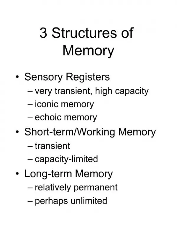
Read/write memory (R/W memory) : is computer storage that allows data to be both easily accessed (read) and modified (written) using electrical signals, with RAM (Random Access Memory) being the most common example, acting as temporary, volatile storage for active data and programs, enabling fast data interaction by the CPU, with common types including faster SRAM (for caches) and cheaper DRAM (for main system memory). Key Characteristics Bidirectional Access: Data can be retrieved (read) or saved/changed (written). Volatile: Most types (like DRAM) lose their data when power is removed, hence the need for storage. Random Access: The CPU can access any memory location directly and quickly, unlike sequential storage. Control Signals: A Read/Write signal determines the operation, along with address and data strobes. Common Types of Read/Write Memory DRAM (Dynamic RAM): Used as main system memory (e.g., DDR4, DDR5), stores data in capacitors that need refreshing. SRAM (Static RAM): Faster and more expensive, used for CPU cache, doesn't need refreshing. How it Works (Simplified): Address: CPU places the memory address on the address bus. Read/Write Signal: CPU sets a signal to indicate read or write. Data Transfer: Memory places data on the data bus (read) or accepts data from the bus (write). Strobes: Signals like Address Strobe and Data Strobe manage timing and confirm data validity. Examples of Use Main Memory (RAM): Holds operating system, running apps, and active files for fast access. Cache Memory (SRAM): Very fast, small memory within the CPU for frequently used data. Storage Devices: Hard drives, SSDs, and USB drives also have read/write capabilities, though they are non-volatile.
DRAM Cell Ccell must be small to obtain high density, but big enough to obtain voltage swing at read.
bit0 bit1 bit511 word0 word1 word255 Like SRAMs, large DRAMs are divided into sub-arrays, whose size represents a tradeoff between area and performance. Large sub-arrays amortize sense amplifiers and decoders among more cells but are slower and have less swing due to higher capacitance of word and bit lines. Bit-line capacitance is far larger than cell, hence voltage swing ΔV during read is very small and sense amplifier is used.
Open bit-line architecture Is useful for small DRAMs. It has dense layout but sense amps are exposed to differential noise since their inputs come from different sub-arrays, while word line is asserted in one array. Folded bit-line architecture solves the problem of differential noise on the account of area expansion. Sense amps input are connected to adjacent bit-lines exposed to similar noise sources. When a word-line is asserted, one bit line is being read while its neighbor serves as the quiet reference. Smart layout and aggressive manufacturing design rules (e.g. 45 degrees polygons) enable effective area increase of only 33%.
Sub-array 1 Word-Line Decoders Word-Line Decoders Sense Amps Word-Line Decoders Word-Line Decoders Sub-array 2 Open Bit-Line Architecture
Sense Amps Word-Line Decoders Word-Line Decoders Sense Amps Folded Bit-Line Architecture
Polysilicon Word-Line Metal Bit-Line Word-Line Decoder Word-Line Decoder Word-Line Decoder Word-Line Decoder n+ Diffusion Bit-Line Contact Capacitor Sense Amp Sense Amp
Vp P2 P1 N1 N2 Vn bit’ bit” DRAM Sense Amp bit’ and bit” are initialized to VDD/2. Vp=0 and Vn= VDD/2, so all transistors are initially OFF. During read one bit-line is changing while the other stays float in VDD/2. Let bit’ change to 0. Once it reaches VDD/2-Vt, N1 conducts and it follows bit’. Hence Vn is pulled down. Meanwhile bit” is pulled up, which opens P2 and raise Vp to VDD.
VDD Bit” VDD/2 Bit’ 0 VDD VDD/2 Vn Vp 0


![[Array, Array, Array, Array, Array, Array, Array, Array, Array, Array, Array, Array]](https://cdn1.slideserve.com/2223440/array-array-array-array-array-array-array-array-array-array-array-array-dt.jpg)