Download
1 / 8
0 likes | 20 Views
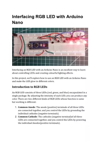
In this project, we'll explore how to use an RGB LED with an Arduino Nano and make the LED glow in different colors.<br>

E N D
Interfacing RGB LED with Arduino Nano Interfacing an RGB LED with an Arduino Nano is an excellent way to learn about controlling LEDs and creating colourful lighting effects. In this project, we'll explore how to use an RGB LED with an Arduino Nano and make the LED glow in different colors. Introduction to RGB LEDs An RGB LED consists of three LEDs (red, green, and blue) encapsulated in a single package. By adjusting the intensity of each LED, you can produce any color. There are two different kinds of RGB LEDs whose function is same but working is different: 1. Common Anode: The anode (positive) terminals of all three LEDs are connected together, and you control the LEDs by grounding the individual cathodes (negative terminals). 2. Common Cathode: The cathodes (negative terminal)of all three LEDs are connected together, and you control the LEDs by powering the individual Anodes(positive terminals).
How RGB LEDs Work? The principle behind RGB LEDs is color mixing. By adjusting the current flowing through each of the red, green, and blue LEDs, different colors can be produced. For example: ● When all three LEDs are at full brightness, the result is white light. ● When only the red and green LEDs are on, the result is yellow light. ● When only the green and blue LEDs are on, the result is cyan light. The color produced by an RGB LED is determined by the combination and intensity of the red, green, and blue LEDs. This can be controlled using pulse width modulation (PWM), which varies the duty cycle of the current supplied to each LED. Color Mixing Chart To better understand how to combine colors, refer to a basic color mixing chart. This chart shows the combination of red, green, and blue intensities to produce various colors.
Color Red Intensity Green Intensity Blue Intensity Red High Low Low Green Low High Low Blue Low Low High White High High High Yellow High High Low Cyan Low High High Magenta High Low High Purple Medium Low High Orange High Medium Low Understanding the Pin Configuration of common cathode RGB LED This LED typically has four pins: 1. Common Cathode Pin: This pin is connected to the ground (GND). 2. Red Pin: Controls the red segment of the LED. 3. Green Pin: Controls the green segment of the LED.
4. Blue Pin: Controls the blue segment of the LED. Producing Vibrant colors using RGB LEDs and an Arduino Nano Components Required To get started, you'll need the following components: 1. Arduino Nano 1 2. RGB LED ( common cathode ): 3 nos 3. Resistors(220 ohm) : 3 nos 4. Breadboard(full size) : 1 5. Jumper Wires : multiple 6. BC547 (NPN transistor) : 3 nos Circuit Diagram The RGB LED has four pins: one common anode (CA) and three cathodes for the red, green, and blue LEDs. The common anode is connected to a 5V power supply, and each cathode is connected to the collector of an NPN transistor. The emitters of the transistors are connected to the ground. The bases of the transistors are connected to Arduino pins D6, D5, and D3.
The Arduino Nano is powered by the 5V supply, with its 5V and GND pins connected to the positive and negative rails of the breadboard, respectively. The use of transistors allows the Arduino to control the higher current needed by the RGB LED, while the resistors ensure that the base current of the transistors is within safe limits. This setup is a common method for RGB LED control in various electronics projects, enabling a wide range of color mixing and lighting applications. Here is the schematics of the above wiring diagram: In the above schematics if you want you add more LED’s then you can add more LEDs. Two changes must be done in above circuit: 1. A base resistance needs to be added so as to limit the current though Aduino pin. In current configuration also you can add a 1k base resistance. 2. Choose a NPN transistor of higher current rating so as to run multiple LED’s. No changes in code required for multiple LED’s.
Arduino Code This Arduino sketch is designed to control the brightness of three LEDs (Red, Green, and Blue) using Pulse Width Modulation (PWM). By varying the duty cycle of the PWM signals sent to these LEDs, the sketch creates a smooth transition of colors. // Pin definitions const int RedLed = 6; // Red LED connected to pwm pin 6 const int GreenLed = 5; // Green LED connected to pwm pin 5 const int BlueLed = 3; // Blue LED connected to pwm pin 3 void setup() { // Initialize PWM pins as outputs pinMode(RedLed, OUTPUT); pinMode(GreenLed, OUTPUT); pinMode(BlueLed, OUTPUT); } void loop() { int index1, index2; analogWrite(GreenLed, 255); // Green for (index1 = 0; index1 < 256; index1++) { for (index2 = 0; index2 < 256; index2++) { analogWrite(RedLed, index1); // Red analogWrite(BlueLed, index2); // Blue } } analogWrite(BlueLed, 255); // Blue
for (index1 = 0; index1 < 256; index1++) { for (index2 = 0; index2 < 256; index2++) { analogWrite(GreenLed, index1); // Green analogWrite(RedLed, index2); // Red } } analogWrite(RedLed, 255); // Red for (index1 = 0; index1 < 256; index1++) { for (index2 = 0; index2 < 256; index2++) { analogWrite(GreenLed, index1); // Green analogWrite(BlueLed, index2); // Blue } } } Code Explanation Pin Definitions: ● Red LED is connected to PWM pin 6. ● Green LED is connected to PWM pin 5. ● Blue LED is connected to PWM pin 3. Setup Function: ● The setup function runs once when the Arduino is powered on or reset. ● It initializes the three LED pins as outputs using the pinMode function. Loop Function:
● The loop function runs continuously, creating the color-mixing effect. 1. First Color Mixing Sequence (Green and Blue with varying Red): ○ Sets the Green LED to full brightness (255). ○ Two nested for loops iterate through index1 and index2 from 0 to 255. ○ Within the inner loop, the brightness of the Red LED (index1) and the Blue LED (index2) are adjusted using analogWrite. ○ This creates a gradient effect where the Red and Blue LEDs blend with the Green LED. 2. Second Color Mixing Sequence (Blue and Red with varying Green): ○ Sets the Blue LED to full brightness (255). ○ The nested loops iterate again. ○ This time, the brightness of the Green LED (index1) and the Red LED (index2) are adjusted. ○ This creates a gradient effect where the Green and Red LEDs blend with the Blue LED. 3. Third Color Mixing Sequence (Red and Blue with varying Green): ○ Sets the Red LED to full brightness (255). ○ The nested loops iterate again. ○ This time, the brightness of the Green LED (index1) and the Blue LED (index2) are adjusted. ○ This creates a gradient effect where the Green and Blue LEDs blend with the Red LED. Related Project RGB LED Interfacing With Arduino UNO