Download
1 / 27
270 likes | 476 Views
Comparison of Single Carrier and Multi-carrier (OFDM) PSK transmission schemes in Multi-path Wireless channel. Professor : Dr. Pao Lo Liu Teaching Assistant: Saurav Bandyopadhyay. Group Members: Asghar Hasnain Anantakrishna Varanasi Pavan Venugopal. Presentation Outline.

E N D
Comparison of Single Carrier and Multi-carrier (OFDM) PSK transmission schemes in Multi-pathWireless channel Professor : Dr. Pao Lo Liu Teaching Assistant: Saurav Bandyopadhyay Group Members: Asghar Hasnain Anantakrishna Varanasi Pavan Venugopal
Presentation Outline • Understanding Multipath Wireless channel and ISI • OFDM and OFDM Block Diagram • Our approach • MATLAB Implementation – Block by Block explanation • Simulation Results • Conclusion
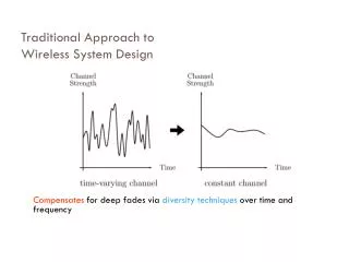
Characteristics of a Multipath Wireless Channel • Delay Spread – It is the interval for which a symbol remains inside the multi path channel. • Channel can be modeled as a FIR filter with one line of sight path and several multipaths , the signals from the multipaths being delayed and attenuated version of the signal from the line of sight path.
Inter Symbol Interference and its Solution • High Data rate requires smaller symbol period • If symbol period < delay spread then we have ISI. • Effect of Modulation Scheme and Symbol period on ISI. • BER BER
Solution to ISI • Having multiple carriers and making the symbol period on each carrier higher than the delay spread of the channel . • Effective rate will be high because we are using multiple carriers (serial to parallel conversion). • This is similar to FDM where we use different carriers in non-overlapping frequency bands – NOT BANDWIDTH EFFICIENT • In OFDM due to the orthogonality property of the carriers we place them as close as possible ensuring bandwidth efficiency.
A Qualitative Description of OFDM • OFDM stands for Orthogonal Frequency Division Multiplexing. • OFDM is based on a parallel data transmission scheme that reduces the effect of multipath fading and makes the use of complex equalizers unnecessary. • OFDM is derived from the fact that the digital data is sent using many carriers, each of a different frequency and these carriers are orthogonal to each other, hence Orthogonal Frequency Division Multiplexing . The frequency spacing of the carriers is chosen in such a way that the modulated carriers are orthogonal and do not interfere with one another.
Our approach • To use MATLAB to simulate a multi path (frequency selective fading) channel for a given number of Multi Paths. We will explain and use the FIR filter model of a Frequency Selecting Fading Channel. • Simulate Modulator and Demodulator Structures for the Single and Multi Carrier PSK Transmission System along with proper “Symbol Generation” system to simulate Frequency Selective Fading in the Wireless Channel • Employ equal degree of FEC or forward error correction such as Rate Punctured Convolution Encoder/Decoder (RCPC) and compare the BER performance of both the Single and Multi Carrier Transmission systems against symbol period and SNR . • Compare the Results and give a justification if the use of Multi-Carrier Transmission is sensible.
Source Encoder / Decoder ENCODER • The data is usually image, wav or text which is converted into binary data bits. • These bits are then padded with zeros such as to form group of bits to create the symbols based on the modulation scheme. DECODER • At the decoder the recovered bits are put back to get back the original source data.
Channel Encoder/Decoder ENCODER • The data is then encoded for the channel based on the channel rate. • We use RCPC ( Rate Compatible Punctured Convolution Codes). • RCPC is used to give different level of protection for the data bits. The channel rates used are (1/3 , 1/2 and 2/3).
Channel Encoder/Decoder...contd. DECODER • The data recovered is in the form of + 1 and -1 (bipolar form). • The bits recovered from demodulator inserted with zeros at the punctured places--- this is the UNQUANT MODE. • These bits are then decoded using VITERBI Decoder. We use the standard vitdec ( ) function in MATLAB.
Mapping /Recovering Symbols MAPPING of SYMBOLS • We group the bits based on the modulation method selected by the user to form symbols ready for modulation. • For Multicarrier transmission signal we pad the bits with zeros to make it a multiple of sub- carriers . RECOVERING of SYMBOLS • The bits are recovered from the symbols by unpacking the symbols.
The symbols are then modulated and demodulated using the different modulation schemes BPSK Modulation QPSK Modulation 8PSK Modulation 16PSK Modulation 8QAM Modulation 16QAM Modulation 32QAM Modulation 64QAM Modulation Modulation / Demodulation
Generation of FIR filter model to simulate a multipath fading channel • The function takes in the number of multipaths and the delay spread. • It returns a vector ( our channel ) whose length is equal to the delay spread and the number of non zero coeffcients is the given number of multipaths. • We try to implement a Rician Fading Channel which has a LOS path. • Technically, we should choose our Channel Coefficients from a Rician PDF, but we approximated it using a Raleigh PDF.
Single carrier Transmission Scheme • After the Modulator, we employ the following for Single Carrier Transmission Scheme. • The Modulated Data is Delayed and Multiplied with the associated channel coefficient and added to get the channel output. • This signal is corrupted with noise based on the modulation scheme, with BPSK getting Real Noise and Complex Noise for Other Schemes.
Simulation of a multi-carrier system - Transmitter • Using the Spectrum of a Particular symbol we locate the carrier positions in the frequency domain. • We proceed to perform a serial to parallel conversion on the stream of symbols and placing them at the positions of the carriers along with pilot symbols next to them. • We take an IFFT to get the OFDM time signal per block of symbols. We concatenate all the blocks to get the total OFDM time signal • We insert guard time(cyclic prefix) to prevent inter-block interference. • We filter this time signal through an FIR filter and add noise to obtain our received signal
Simulation of a multi-carrier system - Receiver • We remove the Guard Band and divide the time signal into the OFDM blocks. • For Each Block we take the FFT and locate the symbols on interest and also pilot symbols as per the carrier locations. • We try to Estimate the Channel Frequency Response using the Pilot Symbols and use the same to approximately correct the distortion in the desired symbol.
Pilot Signal Transmission Technique • The channel is frequency selective and in order to reconstruct the symbols at the receiver we need the channel response at the position of the symbol. • We insert known pilot symbols very next to our symbols and send them through the same channel filter. • At the receiver we estimate the channel response by using the pilot symbols and take the frequency response of the channel to be the same at the position of the symbol • We correct the distortion in the symbols of interest using the approximate channel response obtained using pilot symbols.
Insertion of guard time (cyclic prefixing) Our function inserts the Cyclic Prefix to serve as a Guard time for the OFDM time signal. The length of the Guard Time (M) is chosen to be the length of the filter. We basically copy the last M samples of the previous block and attach it to the beginning of the current block.
SIMULATION RESULTS SINGLE CARRIER SINGLE CARRIER MULTI CARRIER MULTI CARRIER
SINGLE CARRIER SINGLE CARRIER MULTI CARRIER MULTI CARRIER
Conclusions and Future Work • Conclusions: • Multi Carrier Outperforms Single Carrier Transmission Schemes for a Given Channel and Equal Degree of FEC at a particular high data rate. • Future Work: • Implementation of the same with Time Varying Channel and Rician Fading Coefficients. • Addressing the Problem of Peak to Average Power Problem in OFDM.