Download
1 / 24
340 likes | 1.25k Views
DESIGN AND DEVELOPMENT OF AN ECONOMICAL TORSION TESTING MACHINE. by Glenn Vallee, Ph.D., P.E. And Robert Short Mechanical Engineering Department Western New England College. Project Objectives. Design and build a torsion testing machine capable of performing the ASTM Torsion Test

E N D
DESIGN AND DEVELOPMENT OF AN ECONOMICAL TORSION TESTING MACHINE by Glenn Vallee, Ph.D., P.E. And Robert Short Mechanical Engineering Department Western New England College
Project Objectives • Design and build a torsion testing machine capable of performing the ASTM Torsion Test • Machine must measure material properties to within 5% of published data • Machine must be affordable
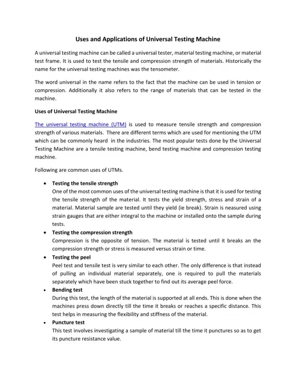
Torsion Testing Apparatus • Experimentally determines torsional shear properties of materials • A cylindrical test specimen is twisted until failure • Applied torque and angle of twist are recorded • ASTM Standardized Test Method Used- Specifies Test Procedure / Specimen Geometry
Design Constraints • Machine must be capable of fracturing a steel test specimen • Specimen diameter to be 3/8 inch to allow examination of fracture surfaces- ASTM therefore requires a specimen length of 6 inches to meet the min length/diameter ratio • Torque and angle of twist measuring devices to be easily accessible to students
Design Constraints • Machine must produce measurements within 5% of published ASTM results • Budget allocation of $500 • Many Years of Service!!!
Determination of Shear Properties • Elementary mechanics theory used to relate applied torque, T to shear stress, τusing • Eq. (1) where ρ = radius of the specimen cross section J = polar moment of inertia of cross section • Shear strain γ is calculated using • Eq. (2) γ= ρθ/L • where L = specimen lengthθ = angle of twist
Determination of Shear Properties • Shear Modulus G is determined by finding the slope of the shear tress-strain diagram • Shear modulus may also be calculated using Eq. (3)
Design – Torque and Angle of Twist Requirements • Equation (1) was used to estimate the torque required to yield a C1018 plane carbon steel test specimen in torsion • 3000 in-lb would be required to fail C1018 material at constant rotational velocity • Experiments were performed using aluminum to find required angle of twist (10 revolutions)
Drive Train • A DC motor with an integral gear reduction and speed controller was used • A sprocket set having a 6:1 gear ratio developed required torque
Frame Design • Two inch square steel channel was welded together to form the frame Base Frame / Motor Sub Assembly
Measurement of Torque • A torque gauge was fitted to thefixed hub Gage mounted on a 45° Angle Torque Gage
Measurement of Torque • Strain Gauge aligned with direction of Max Principle Stress (kpsi) max σ2 = State of Pure Shear 2Ө σ2 σ1 σ (kpsi) 45° σ1 =
Measurement of Angle of Twist • A potentiometer was mounted to a wheel which contacted the rotating hub. Weight Potentiometer Sprocket Wheel
Chuck Alignment • A T-slide was used to prevent development of axial loads and to aid in alignment
Torque Calibration • A weighted lever system was used to calibrate the torque gauge Gage Fabricated Torque Wrench
Complete Assembly Strain Gauge Leads Potentiometer Leads Motor Speed Control Power Switches / LEDs
Performance • Data Collection with Lab VIEW • Testing of 1018 Cold Drawn Steel • Shear modulus measured as 10.7 Mpsi, 3% lower than the published value • Testing of 2014 Aluminum • Shear modulus measured as 3.7 Mpsi, 5% lower than the published value
Integration Into the ME Curriculum • Torsion machine has been integrated in two ways- ASTM torsion experiment has been included in the junior laboratory sequence- design and use of the torsion machine is introduced in the sophomore Mechanics of Materials course
Junior Laboratory Experience • Students examine the torque cell and calculate its limiting torsional strength • Students create calibration curves for the torque cell and rotational potentiometer • Steel and aluminum specimens are tested o failure and the results are compared to published data
Mechanics of Materials Course • Students examine the torque cell and calculate its limiting torsional strength • ASTM torsion test is performed in class • Students determine the shear stress-strain diagram for steel and aluminum and determine their shear modulii • Shear failure surfaces are examined