Download
1 / 33
370 likes | 959 Views
Fundamentals Of Electricity. Simple DC Series Circuit, . R t = R 1 +R 2 +R 3. Simple DC Parallel Circuit, . R t = (R 1 .R 2 .R 3 ) /(R 2 .R 1 +R 3 .R 2 +R 1 .R 3 ) . Fundamentals Of Electricity. Simple AC Series Circuit, . Simple AC Parallel Circuit, . Fundamentals Of Electricity.

E N D
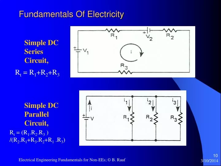
Fundamentals Of Electricity Simple DC Series Circuit, Rt = R1+R2+R3 Simple DC Parallel Circuit, Rt = (R1.R2.R3 ) /(R2.R1+R3.R2+R1 .R3) Electrical Engineering Fundamentals for Non-EEs; © B. Rauf
Fundamentals Of Electricity Simple AC Series Circuit, Simple AC Parallel Circuit, Electrical Engineering Fundamentals for Non-EEs; © B. Rauf
Fundamentals Of Electricity Three Phase (AC) Transformer Configurations Note: a = Turns Ratio = Np/Ns Electrical Engineering Fundamentals for Non-EEs; © B. Rauf
Fundamentals Of Electricity Impedance: • Definition : Impedance is the current resisting and impeding characteristic of load or conductor in an AC Circuit. • Symbol for Impedance: Z Z = R + jXl - jXc Where, jXl = Zl and, -jXc =Zc • Unit for Impedance: Ohms or s. Electrical Engineering Fundamentals for Non-EEs; © B. Rauf
Fundamentals Of Electricity Ohms Law: • Mathematical Statement of the Ohm’s Law: V= I Rfor DC circuits V = I Z for AC Circuits Note:BOLD letters, in general, represent Vectoral quantities Electrical Engineering Fundamentals for Non-EEs; © B. Rauf
Impedance Calculation: Electrical Engineering Fundamentals for Non-EEs; © B. Rauf
Fundamentals Of Electricity Power : • Definition:Power is defined as the capacity of a system to perform work or Rate of work performed by a system. • Symbols and Types of Power: • Pdc= V.I , in watts. Note: Pdc= Preal Papparent= S= Apparent Power (kVA) or Total AC Power Preal = P = Real Power Comp. of Apparent Power, in kW Preactive= Q = Reactive Comp. of App. Power in kVAR • Pappent = (Preal)2+(Preactive)2 orS= (P)2+(Q)2 • Magnitude of Total (3 ) Power = S= 3. VL.IL Electrical Engineering Fundamentals for Non-EEs; © B. Rauf
Fundamentals Of Electricity Power Factor : • Definition: Power Factor is defined as the Ratio of Real Power (kW) to Apparent Power (kVA). It is also defined as the quantity cos( - ). PF = P/S or PF = cos( - ), • where is the angle of voltage V, whereV = VRMS • is the angle of current i = I RMS Note:Detailed discussion on the topic of Power Factor is covered under the Power Factor segment of this seminar. Electrical Engineering Fundamentals for Non-EEs; © B. Rauf
Fundamentals Of Electricity Voltage Regulation: Definition: Real voltage sources are unable to hold the voltage constant as they assume a significant amount of load (Resistance or Impedance). This results in the difference between Vno load and Vfull load. The formula for Voltage Regulation is as follows: Voltage Reg. = (Vno load - Vfull load)/ Vfull load x 100% Electrical Engineering Fundamentals for Non-EEs; © B. Rauf
Fundamentals Of Electricity Service Factor of a Motor: Definition: Service factor of a motor is the ratio of safe to standard (nameplate) loads. Service factor is expressed in decimal. The formula for Service Factor is as follows: Service Factor = Safe Load / Nameplate Load Electrical Engineering Fundamentals for Non-EEs; © B. Rauf
Fundamentals Of Electricity Classifications of Motors: • Motor categorization by NEMA, National Electrical Manufacturers Association: • Speed: • Constant Speed • Adjustable Speed • Multispeed • Varying Speed • Service Classification: • General • Definite • Special Purpose • Varying Speed Electrical Engineering Fundamentals for Non-EEs; © B. Rauf
Fundamentals Of Electricity Classifications of Motors, contd.: • Motor Class is determined by the maximum allowable operating temperature of the motor, which is dependant on the type/grade of insulation used in the motor. • Class A: 105 C • Class B: 130 C • Class F: 155 C • Class H: 180 C Electrical Engineering Fundamentals for Non-EEs; © B. Rauf
Fundamentals Of Electricity Kirchhoff’s Voltage Law (KVL): Algebraic sum of voltage drops around any closed path, within a circuit, is equal to the sum of voltages presented by all of the voltage sources. The mathematical representation of KVL is as follows: VDrops = VSource Electrical Engineering Fundamentals for Non-EEs; © B. Rauf
Fundamentals Of Electricity Kirchhoff’s Current Law (KCL): Total current flowing into a node is equal to the total current that flows out of the node. The mathematical representation of KCL is as follows: iin = iout Electrical Engineering Fundamentals for Non-EEs; © B. Rauf
Fundamentals Of Electricity Motor Speed Calculation: • Given: Number of Poles = P = 4 Frequency of AC Power Supply to the Motor, in Hertz = f = 60 Hz Speed, in RPM = S = ? • Formula: S x P = 120 x f • S = (120 x f ) / P • S = (120 x 60) / 4 = 1800 RPM Electrical Engineering Fundamentals for Non-EEs; © B. Rauf
Fundamentals Of Electricity Motor Slip: Slip is usually expressed in percent and can be computed as follows: Percent slip = (Synchronous speed - Actual speed ) x 100 Synchronous Speed • Induction motors are made with slip ranging from less than 5% up to 20%. • A motor with a slip of 5% or less is known as a normal-slip motor. A normal-slip motor is sometimes referred to as a 'constant speed' motor because the speed changes very little from no-load to full-load conditions. A common four-pole motor with a synchronous speed of 1,800 rpm may have a no-load speed of 1,795 rpm and a full-load speed of 1,750 rpm. The rate-of-change of slip is approximately linear from 10% to 110% load, when all other factors such as temperature and voltage are held constant. Motors with slip over 5% are used for hard to start applications. The direction of rotation of a polyphase ac induction motor depends on the connection of the stator leads to the power lines. Interchanging any two input leads reverses rotation. Electrical Engineering Fundamentals for Non-EEs; © B. Rauf
Fundamentals Of Electricity Motor Torque, Power and Horsepower: • Torque is equivalent to the amount of work performed. Torque can be considered as turning effort. For example, suppose a wheel with a crank arm one-foot long takes a force of one pound to turn at steady rate. The torque required would be one pound times one foot or one foot-pound. • Horsepower, i .e. Power, is defined as the rate at which work is performed or rate at which torque is produced. • In the wheel cranking example above, if one were to crank the wheel twice as fast, the torque remains the same but the power and horsepower delivered would double, regardless of how fast the crank is turned, as long as the crank is turned at a steady speed. Electrical Engineering Fundamentals for Non-EEs; © B. Rauf
Fundamentals Of Electricity Motor Torque and Horsepower, contd.: • Power, Horsepower and Torque Relationship: Torque(ft-lbf) = 5250 x P (horsepower) Speed(rpm) Torque(N-m) = 9549 x P (kW) Speed(rpm) Electrical Engineering Fundamentals for Non-EEs; © B. Rauf
Fundamentals Of Electricity in Industrial and Commercial Environment Motor Power – Line Current Calculation: • Motor Nameplate Information: Power rating, in HP (Horse Power) = P = 10 HP Voltage Rating = 480 VAC No. of Phases = 3; also stated as 3 Power Factor = PF = 0.8 Efficiency = Eff. = 0.9 Magnitude of Line Current = FLA, Full Load Current = I = I = ? Note: 1 HP = 746 Watts = 746 W = 0.746 kW Formula: I = Power in Watts / PF / Eff./ (3 x VL) • I = 10HP x 746 W/HP/0.8/0.9/(3 x480VAC) • I = 12.46 Amps Electrical Engineering Fundamentals for Non-EEs; © B. Rauf
Fundamentals Of Electricity Miscellaneous: • Demand: This term means the highest average power (kW) in a given interval, or demand interval. Electric utilities charge commercial and industrial customers for the peak demand set each month. • Peak demand: This is the maximum demand used in any demand interval for a given month. • Load factor: The load factor is the ratio of average power to peak demand. Utility customers are sometimes penalized for low load factor that can occur when large amounts of power are used in short periods of time, instead of at a steady rate for long periods of time. Electrical Engineering Fundamentals for Non-EEs; © B. Rauf
Electronics Semiconductor Diode: Electrical Engineering Fundamentals for Non-EEs; © B. Rauf
Electronics Outputs From Simple Diode Circuits: Electrical Engineering Fundamentals for Non-EEs; © B. Rauf
Outputs From Simple Diode Circuits: Electronics Special Types of Diodes: Electrical Engineering Fundamentals for Non-EEs; © B. Rauf
Electronics Bipolar Junction Transistors: Bipolar Junction Transistor Operating Regions Electrical Engineering Fundamentals for Non-EEs; © B. Rauf
Standards • NEMA: National Electrical Manufacturers Association; www.nema.org • NEMA, created in the fall of 1926 by the merger of the Electric Power Club and the Associated Manufacturers of Electrical Supplies, provides a forum for the standardization of electrical equipment, enabling consumers to select from a range of safe, effective, and compatible electrical products. • ANSI: American National Standards Institute; www.ansi.org • The American National Standards Institute (ANSI) is a private, non-profit organization that administers and coordinates the U.S. voluntary standardization and conformity assessment system • IEC: International Electrotechnical Commission. • IEC is the authoritative worldwide body responsible for developing consensus global standards in the electrotechnical field Electrical Engineering Fundamentals for Non-EEs; © B. Rauf
Standards • IEEE: Institute of Electrical and Electronic Engineers; www.ieee.org • The IEEE is a non-profit, technical professional association for Electrical and Electronics Engineers. Electrical Engineering Fundamentals for Non-EEs; © B. Rauf
Power Distribution Systems Power Distribution Systems Consist of: • MCC or Motor Control Centers • Loop Switches • Transformers • Voltage Regulators • Capacitor Banks • Circuit Breakers • OCB’s, Oil Circuit Breakers • Air Circuit Breakers • Disconnect Switches • Fuses • Starters and Combination Starters • Power Monitoring and Control Systems Electrical Engineering Fundamentals for Non-EEs; © B. Rauf
Power Factor Correction Bobby Rauf © • 1 Electrical Engineering Fundamentals for Non-EE's; © B. Rauf 3/10/2014
Topics Power Factor, Definition, Concept and Formulas Power Factor Correction / Improvement Example Additional Comments / Discussion on Power Factor Power Factor and Loss Calculation Example • 2 Electrical Engineering Fundamentals for Non-EE's; © B. Rauf 3/10/2014
Fundamentals Of Electricity Power Factor, Definition, Concept and Formula: Definition: Power Factor is defined as the Ratio of Real Power (kW) to Apparent Power (kVA). It is also defined as the quantity cos( - ). PF = P/S or PF = cos( - ), where is the angle of voltage V, whereV = VRMS is the angle of current i = I RMS % PF = (PF) x 100 • 3 Electrical Engineering Fundamentals for Non-EE's; © B. Rauf 3/10/2014
Fundamentals Of Electricity Power Factor, contd.: Leading Power Factor: Power factor is said to be leading when, the angle of the current, exceeds , the angle of the voltage. In other words, ( - ) is negative. Impedance, Zc, due to pure capacitance reactance, Xc, has a negative angle. Or, Zc = Xc -90 I Zc= Xc -90=-j Xc - V • 4 Electrical Engineering Fundamentals for Non-EE's; © B. Rauf 3/10/2014
Fundamentals Of Electricity Power Factor, contd.: Lagging Power Factor: Power factor is said to be lagging when, the angle of the current, is less than , the angle of the voltage. In other words, ( - ) is positive. Impedance, Zl, due to pure inductive reactance, Xl, has a positive angle. Or, Zl = Xl 90 In Inductive Circuits, add Capacitance, or Capacitive Reactance, Xc, to offset the Inductive Reactance, Xl, and to Increase the PF. V Zl= Xl +90=+j Xl Pf Angle = - I V 90 Deg. I • 5 V Electrical Engineering Fundamentals for Non-EE's; © B. Rauf 3/10/2014
Fundamentals Of Electricity Power Factor, contd : C = ( Q1 - Q2 ) 2 f V2 Where, C = Capacitance (F) required to reduce the Reactive or Imaginary Power from Q1 toQ2 Q1 = Initial, higher Reactive Power, in VARs Q2 = Improved, lower Reactive Power, in VARs V = Voltage, in Volts f = Frequency, in Hz • 6 Electrical Engineering Fundamentals for Non-EE's; © B. Rauf 3/10/2014