Download
1 / 7
70 likes | 90 Views
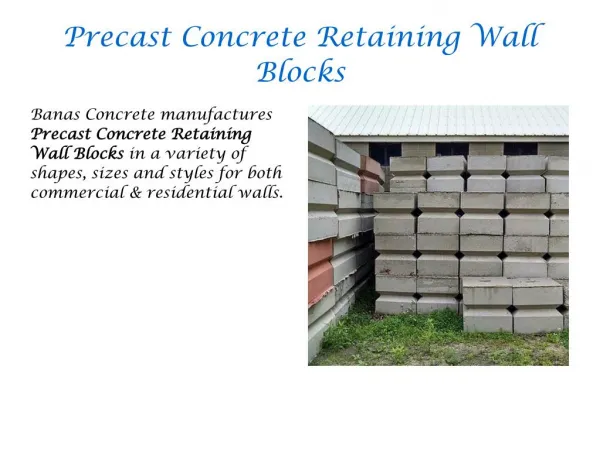
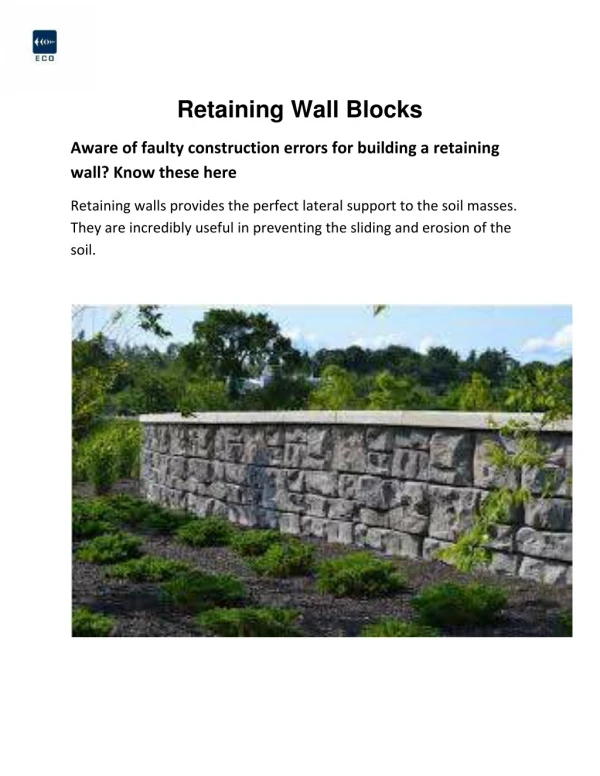
Retaining Wall Geogrid - Mesa Segmental Concrete Facing Units, Used in Conjunction with Tensar Geogrids, Provide an Economical and Aesthetically Attractive Alternative to Conventional Concrete Retaining Walls.<br><br>Visit- https://nilex.com/uniaxial-ux-geogrids/

E N D
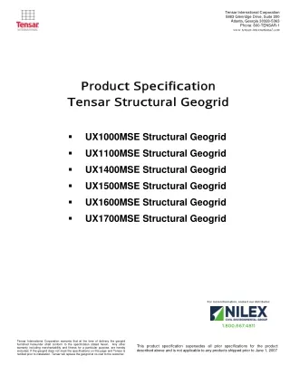
Tensar International Corporation 5883 Glenridge Drive, Suite 200 Atlanta, Georgia 30328-5363 Phone: 800-TENSAR-1 www.tensar-international.com Produc t S pec ific ation T ensar S truc tural Geogrid Produc t S pec ific ation T ensar S truc tural Geogrid ? UX1000MSE Structural Geogrid ? UX1100MSE Structural Geogrid ? UX1400MSE Structural Geogrid ? UX1500MSE Structural Geogrid ? UX1600MSE Structural Geogrid ? UX1700MSE Structural Geogrid For more information, contact our distributor: 1.800.667.4811 Tensar International Corporation warrants that at the time of delivery the geogrid furnished hereunder shall conform to the specification stated herein. Any other warranty including merchantability and fitness for a particular purpose, are hereby excluded. If the geogrid does not meet the specifications on this page and Tensar is notified prior to installation, Tensar will replace the geogrid at no cost to the customer. This product specification supersedes all prior specifications for the product described above and is not applicable to any products shipped prior to June 1, 2007
Tensar International Corporation 5883 Glenridge Drive, Suite 200 Atlanta, Georgia 30328-5363 Phone: 800-TENSAR-1 www.tensar-international.com Product Specification - Structural Geogrid UX1000MSE Tensar International Corporation reserves the right to change its product specifications at any time. It is the responsibility of the specifier and purchaser to ensure that product specifications used for design and procurement purposes are current and consistent with the products used in each instance. Product Type: Polymer: Load Transfer Mechanism: Recommended Applications: Product Properties Integrally Formed Structural Geogrid High Density Polyethylene Positive Mechanical Interlock MESA System (Segmental Block Walls), SierraScape System (Welded Wire Walls) MD Values1 23 (1,570) 46 (3,150) Units kN/m (lb/ft) kN/m (lb/ft) Index Properties ? Tensile Strength @ 5% Strain2 ? Ultimate Tensile Strength2 ? Junction Strength3 ? Flexural Stiffness4 Durability ? Resistance to Long Term Degradation5 ? Resistance to UV Degradation6 Load Capacity ? Maximum Allowable (Design) Strength for 120-year Design Life7 Recommended Allowable Strength Reduction Factors7 ? Minimum Reduction Factor for Installation Damage (RFID)8 ? Reduction Factor for Creep for 120-year Design Life (RFCR) 9 ? Minimum Reduction Factor for Durability (RFD) Dimensions and Delivery The structural geogrid shall be delivered to the jobsite in roll form with each roll individually identified and nominally measuring 1.33 meters (4.36 feet) in width and 76.2 meters (250.0 feet) in length. A typical truckload quantity is 432 rolls. kN/m (lb/ft) mg-cm % % kN/m (lb/ft) 43 (2,950) 400,000 100 95 16.8 (1,150) 1.05 2.60 1.00 Notes: 1. Unless indicated otherwise, values shown are minimum average roll values determined in accordance with ASTM D4759-02. Brief descriptions of test procedures are given in the following notes. 2. True resistance to elongation when initially subjected to a load measured via ASTM D6637-01 without deforming test materials under load before measuring such resistance or employing "secant" or "offset" tangent methods of measurement so as to overstate tensile properties. 3. Load transfer capability determined in accordance with GRI-GG2-05. 4. Resistance to bending force determined in accordance with ASTM D5732-01, using specimen dimensions of 864 millimeters in length by one aperture in width. 5. Resistance to loss of load capacity or structural integrity when subjected to chemically aggressive environments in accordance with EPA 9090 immersion testing. 6. Resistance to loss of load capacity or structural integrity when subjected to 500 hours of ultraviolet light and aggressive weathering in accordance with ASTM D4355-05. 7. Reduction factors are used to calculate the geogrid strength available for resisting force in long-term load bearing applications. Allowable Strength (Tallow) is determined by reducing the ultimate tensile strength (Tult) by reduction factors for installation damage (RFID), creep (RFCR) and chemical/biological durability (RFD = RFCD⋅RFBD) per GRI-GG4-05 [Tallow = Tult/(RFID⋅RFCR⋅RFD)]. Recommended minimum reduction factors are based on product-specific testing. Project specifications, standard public agency specifications and/or design code requirements may require higher reduction factors. Design of the structure in which the geogrid is used, including the selection of appropriate reduction factors and design life, is the responsibility of the outside licensed professional engineer providing the sealed drawings for the project. 8. Minimum value is based on Installation Damage Testing in Sand, Silt, and Clay soils. Coarser soils require increased RFID values. 9. Reduction Factor for Creep determined for 120-year design life and in-soil temperature of 20°C using standard extrapolation techniques to creep rupture data obtained following the test procedure in ASTM D5262-04. Actual design life of the completed structure may differ. Tensar International Corporation warrants that at the time of delivery the geogrid furnished hereunder shall conform to the specification stated herein. Any other warranty including merchantability and fitness for a particular purpose, are hereby excluded. If the geogrid does not meet the specifications on this page and Tensar is notified prior to installation, Tensar will replace the geogrid at no cost to the customer. This product specification supersedes all prior specifications for the product described above and is not applicable to any products shipped prior to June 1, 2007
Tensar International Corporation 5883 Glenridge Drive, Suite 200 Atlanta, Georgia 30328-5363 Phone: 800-TENSAR-1 www.tensar-international.com Product Specification - Structural Geogrid UX1100MSE Tensar International Corporation reserves the right to change its product specifications at any time. It is the responsibility of the specifier and purchaser to ensure that product specifications used for design and procurement purposes are current and consistent with the products used in each instance. Product Type: Polymer: Load Transfer Mechanism: Recommended Applications: Product Properties Integrally Formed Structural Geogrid High Density Polyethylene Positive Mechanical Interlock MESA System (Segmental Block Walls), SierraScape System (Welded Wire Walls) MD Values1 27 (1,850) 58 (3,970) Units kN/m (lb/ft) kN/m (lb/ft) Index Properties ? Tensile Strength @ 5% Strain2 ? Ultimate Tensile Strength2 ? Junction Strength3 ? Flexural Stiffness4 Durability ? Resistance to Long Term Degradation5 ? Resistance to UV Degradation6 Load Capacity ? Maximum Allowable (Design) Strength for 120-year Design Life7 Recommended Allowable Strength Reduction Factors7 ? Minimum Reduction Factor for Installation Damage (RFID)8 ? Reduction Factor for Creep for 120-year Design Life (RFCR) 9 ? Minimum Reduction Factor for Durability (RFD) Dimensions and Delivery The structural geogrid shall be delivered to the jobsite in roll form with each roll individually identified and nominally measuring 1.33 meters (4.36 feet) in width and 76.2 meters (250.0 feet) in length. A typical truckload quantity is 432 rolls. kN/m (lb/ft) mg-cm % % kN/m (lb/ft) 54 (3,690) 500,000 100 95 21.2 (1,450) 1.05 2.60 1.00 Notes: 1. Unless indicated otherwise, values shown are minimum average roll values determined in accordance with ASTM D4759-02. Brief descriptions of test procedures are given in the following notes. 2. True resistance to elongation when initially subjected to a load measured via ASTM D6637-01 without deforming test materials under load before measuring such resistance or employing "secant" or "offset" tangent methods of measurement so as to overstate tensile properties. 3. Load transfer capability determined in accordance with GRI-GG2-05. 4. Resistance to bending force determined in accordance with ASTM D5732-01, using specimen dimensions of 864 millimeters in length by one aperture in width. 5. Resistance to loss of load capacity or structural integrity when subjected to chemically aggressive environments in accordance with EPA 9090 immersion testing. 6. Resistance to loss of load capacity or structural integrity when subjected to 500 hours of ultraviolet light and aggressive weathering in accordance with ASTM D4355-05. 7. Reduction factors are used to calculate the geogrid strength available for resisting force in long-term load bearing applications. Allowable Strength (Tallow) is determined by reducing the ultimate tensile strength (Tult) by reduction factors for installation damage (RFID), creep (RFCR) and chemical/biological durability (RFD = RFCD⋅RFBD) per GRI-GG4-05 [Tallow = Tult/(RFID⋅RFCR⋅RFD)]. Recommended minimum reduction factors are based on product-specific testing. Project specifications, standard public agency specifications and/or design code requirements may require higher reduction factors. Design of the structure in which the geogrid is used, including the selection of appropriate reduction factors and design life, is the responsibility of the outside licensed professional engineer providing the sealed drawings for the project. 8. Minimum value is based on Installation Damage Testing in Sand, Silt, and Clay soils. Coarser soils require increased RFID values. 9. Reduction Factor for Creep determined for 120-year design life and in-soil temperature of 20°C using standard extrapolation techniques to creep rupture data obtained following the test procedure in ASTM D5262-04. Actual design life of the completed structure may differ. Tensar International Corporation warrants that at the time of delivery the geogrid furnished hereunder shall conform to the specification stated herein. Any other warranty including merchantability and fitness for a particular purpose, are hereby excluded. If the geogrid does not meet the specifications on this page and Tensar is notified prior to installation, Tensar will replace the geogrid at no cost to the customer. This product specification supersedes all prior specifications for the product described above and is not applicable to any products shipped prior to June 1, 2007
Tensar International Corporation 5883 Glenridge Drive, Suite 200 Atlanta, Georgia 30328-5363 Phone: 800-TENSAR-1 www.tensar-international.com Product Specification - Structural Geogrid UX1400MSE Tensar International Corporation reserves the right to change its product specifications at any time. It is the responsibility of the specifier and purchaser to ensure that product specifications used for design and procurement purposes are current and consistent with the products used in each instance. Product Type: Polymer: Load Transfer Mechanism: Recommended Applications: Product Properties Integrally Formed Structural Geogrid High Density Polyethylene Positive Mechanical Interlock MESA System (Segmental Block Walls), ARES System (Panel Walls), SierraScape System (Welded Wire Walls) MD Values1 31 (2,130) 70 (4,800) Units kN/m (lb/ft) kN/m (lb/ft) Index Properties ? Tensile Strength @ 5% Strain2 ? Ultimate Tensile Strength2 ? Junction Strength3 ? Flexural Stiffness4 Durability ? Resistance to Long Term Degradation5 ? Resistance to UV Degradation6 Load Capacity ? Maximum Allowable (Design) Strength for 120-year Design Life7 Recommended Allowable Strength Reduction Factors7 ? Minimum Reduction Factor for Installation Damage (RFID)8 ? Reduction Factor for Creep for 120-year Design Life (RFCR) 9 ? Minimum Reduction Factor for Durability (RFD) Dimensions and Delivery The structural geogrid shall be delivered to the jobsite in roll form with each roll individually identified and nominally measuring 1.33 meters (4.36 feet) in width and 76.2 meters (250.0 feet) in length. A typical truckload quantity is 432 rolls. kN/m (lb/ft) mg-cm % % kN/m (lb/ft) 66 (4,520) 730,000 100 95 25.6 (1,760) 1.05 2.60 1.00 Notes: 1. Unless indicated otherwise, values shown are minimum average roll values determined in accordance with ASTM D4759-02. Brief descriptions of test procedures are given in the following notes. 2. True resistance to elongation when initially subjected to a load measured via ASTM D6637-01 without deforming test materials under load before measuring such resistance or employing "secant" or "offset" tangent methods of measurement so as to overstate tensile properties. 3. Load transfer capability determined in accordance with GRI-GG2-05. 4. Resistance to bending force determined in accordance with ASTM D5732-01, using specimen dimensions of 864 millimeters in length by one aperture in width. 5. Resistance to loss of load capacity or structural integrity when subjected to chemically aggressive environments in accordance with EPA 9090 immersion testing. 6. Resistance to loss of load capacity or structural integrity when subjected to 500 hours of ultraviolet light and aggressive weathering in accordance with ASTM D4355-05. 7. Reduction factors are used to calculate the geogrid strength available for resisting force in long-term load bearing applications. Allowable Strength (Tallow) is determined by reducing the ultimate tensile strength (Tult) by reduction factors for installation damage (RFID), creep (RFCR) and chemical/biological durability (RFD = RFCD⋅RFBD) per GRI-GG4-05 [Tallow = Tult/(RFID⋅RFCR⋅RFD)]. Recommended minimum reduction factors are based on product-specific testing. Project specifications, standard public agency specifications and/or design code requirements may require higher reduction factors. Design of the structure in which the geogrid is used, including the selection of appropriate reduction factors and design life, is the responsibility of the outside licensed professional engineer providing the sealed drawings for the project. 8. Minimum value is based on Installation Damage Testing in Sand, Silt, and Clay soils. Coarser soils require increased RFID values. 9. Reduction Factor for Creep determined for 120-year design life and in-soil temperature of 20°C using standard extrapolation techniques to creep rupture data obtained following the test procedure in ASTM D5262-04. Actual design life of the completed structure may differ. Tensar International Corporation warrants that at the time of delivery the geogrid furnished hereunder shall conform to the specification stated herein. Any other warranty including merchantability and fitness for a particular purpose, are hereby excluded. If the geogrid does not meet the specifications on this page and Tensar is notified prior to installation, Tensar will replace the geogrid at no cost to the customer. This product specification supersedes all prior specifications for the product described above and is not applicable to any products shipped prior to June 1, 2007
Tensar International Corporation 5883 Glenridge Drive, Suite 200 Atlanta, Georgia 30328-5363 Phone: 800-TENSAR-1 www.tensar-international.com Product Specification - Structural Geogrid UX1500MSE Tensar International Corporation reserves the right to change its product specifications at any time. It is the responsibility of the specifier and purchaser to ensure that product specifications used for design and procurement purposes are current and consistent with the products used in each instance. Product Type: Polymer: Load Transfer Mechanism: Recommended Applications: Product Properties Integrally Formed Structural Geogrid High Density Polyethylene Positive Mechanical Interlock MESA System (Segmental Block Walls), ARES System (Panel Walls), SierraScape System (Welded Wire Walls) MD Values1 52 (3,560) 114 (7,810) Units kN/m (lb/ft) kN/m (lb/ft) Index Properties ? Tensile Strength @ 5% Strain2 ? Ultimate Tensile Strength2 ? Junction Strength3 ? Flexural Stiffness4 Durability ? Resistance to Long Term Degradation5 ? Resistance to UV Degradation6 Load Capacity ? Maximum Allowable (Design) Strength for 120-year Design Life7 Recommended Allowable Strength Reduction Factors7 ? Minimum Reduction Factor for Installation Damage (RFID)8 ? Reduction Factor for Creep for 120-year Design Life (RFCR) 9 ? Minimum Reduction Factor for Durability (RFD) Dimensions and Delivery The structural geogrid shall be delivered to the jobsite in roll form with each roll individually identified and nominally measuring 1.33 meters (4.36 feet) in width and 61.0 meters (200.0 feet) in length. A typical truckload quantity is 324 rolls. kN/m (lb/ft) mg-cm % % kN/m (lb/ft) 105 (7,200) 5,100,000 100 95 41.8 (2,860) 1.05 2.60 1.00 Notes: 1. Unless indicated otherwise, values shown are minimum average roll values determined in accordance with ASTM D4759-02. Brief descriptions of test procedures are given in the following notes. 2. True resistance to elongation when initially subjected to a load measured via ASTM D6637-01 without deforming test materials under load before measuring such resistance or employing "secant" or "offset" tangent methods of measurement so as to overstate tensile properties. 3. Load transfer capability determined in accordance with GRI-GG2-05. 4. Resistance to bending force determined in accordance with ASTM D5732-01, using specimen dimensions of 864 millimeters in length by one aperture in width. 5. Resistance to loss of load capacity or structural integrity when subjected to chemically aggressive environments in accordance with EPA 9090 immersion testing. 6. Resistance to loss of load capacity or structural integrity when subjected to 500 hours of ultraviolet light and aggressive weathering in accordance with ASTM D4355-05. 7. Reduction factors are used to calculate the geogrid strength available for resisting force in long-term load bearing applications. Allowable Strength (Tallow) is determined by reducing the ultimate tensile strength (Tult) by reduction factors for installation damage (RFID), creep (RFCR) and chemical/biological durability (RFD = RFCD⋅RFBD) per GRI-GG4-05 [Tallow = Tult/(RFID⋅RFCR⋅RFD)]. Recommended minimum reduction factors are based on product-specific testing. Project specifications, standard public agency specifications and/or design code requirements may require higher reduction factors. Design of the structure in which the geogrid is used, including the selection of appropriate reduction factors and design life, is the responsibility of the outside licensed professional engineer providing the sealed drawings for the project. 8. Minimum value is based on Installation Damage Testing in Sand, Silt, and Clay soils. Coarser soils require increased RFID values. 9. Reduction Factor for Creep determined for 120-year design life and in-soil temperature of 20°C using standard extrapolation techniques to creep rupture data obtained following the test procedure in ASTM D5262-04. Actual design life of the completed structure may differ. Tensar International Corporation warrants that at the time of delivery the geogrid furnished hereunder shall conform to the specification stated herein. Any other warranty including merchantability and fitness for a particular purpose, are hereby excluded. If the geogrid does not meet the specifications on this page and Tensar is notified prior to installation, Tensar will replace the geogrid at no cost to the customer. This product specification supersedes all prior specifications for the product described above and is not applicable to any products shipped prior to June 1, 2007
Tensar International Corporation 5883 Glenridge Drive, Suite 200 Atlanta, Georgia 30328-5363 Phone: 800-TENSAR-1 www.tensar-international.com Product Specification - Structural Geogrid UX1600MSE Tensar International Corporation reserves the right to change its product specifications at any time. It is the responsibility of the specifier and purchaser to ensure that product specifications used for design and procurement purposes are current and consistent with the products used in each instance. Product Type: Polymer: Load Transfer Mechanism: Recommended Applications: Product Properties Integrally Formed Structural Geogrid High Density Polyethylene Positive Mechanical Interlock MESA System (Segmental Block Walls), ARES System (Panel Walls), SierraScape System (Welded Wire Walls) MD Values1 58 (3,980) 144 (9,870) Units kN/m (lb/ft) kN/m (lb/ft) Index Properties ? Tensile Strength @ 5% Strain2 ? Ultimate Tensile Strength2 ? Junction Strength3 ? Flexural Stiffness4 Durability ? Resistance to Long Term Degradation5 ? Resistance to UV Degradation6 Load Capacity ? Maximum Allowable (Design) Strength for 120-year Design Life7 Recommended Allowable Strength Reduction Factors7 ? Minimum Reduction Factor for Installation Damage (RFID)8 ? Reduction Factor for Creep for 120-year Design Life (RFCR) 9 ? Minimum Reduction Factor for Durability (RFD) Dimensions and Delivery The structural geogrid shall be delivered to the jobsite in roll form with each roll individually identified and nominally measuring 1.33 meters (4.36 feet) in width and 61.0 meters (200.0 feet) in length. A typical truckload quantity is 216 rolls. kN/m (lb/ft) mg-cm % % kN/m (lb/ft) 135 (9,250) 6,000,000 100 95 52.7 (3,620) 1.05 2.60 1.00 Notes: 1. Unless indicated otherwise, values shown are minimum average roll values determined in accordance with ASTM D4759-02. Brief descriptions of test procedures are given in the following notes. 2. True resistance to elongation when initially subjected to a load measured via ASTM D6637-01 without deforming test materials under load before measuring such resistance or employing "secant" or "offset" tangent methods of measurement so as to overstate tensile properties. 3. Load transfer capability determined in accordance with GRI-GG2-05. 4. Resistance to bending force determined in accordance with ASTM D5732-01, using specimen dimensions of 864 millimeters in length by one aperture in width. 5. Resistance to loss of load capacity or structural integrity when subjected to chemically aggressive environments in accordance with EPA 9090 immersion testing. 6. Resistance to loss of load capacity or structural integrity when subjected to 500 hours of ultraviolet light and aggressive weathering in accordance with ASTM D4355-05. 7. Reduction factors are used to calculate the geogrid strength available for resisting force in long-term load bearing applications. Allowable Strength (Tallow) is determined by reducing the ultimate tensile strength (Tult) by reduction factors for installation damage (RFID), creep (RFCR) and chemical/biological durability (RFD = RFCD⋅RFBD) per GRI-GG4-05 [Tallow = Tult/(RFID⋅RFCR⋅RFD)]. Recommended minimum reduction factors are based on product-specific testing. Project specifications, standard public agency specifications and/or design code requirements may require higher reduction factors. Design of the structure in which the geogrid is used, including the selection of appropriate reduction factors and design life, is the responsibility of the outside licensed professional engineer providing the sealed drawings for the project. 8. Minimum value is based on Installation Damage Testing in Sand, Silt, and Clay soils. Coarser soils require increased RFID values. 9. Reduction Factor for Creep determined for 120-year design life and in-soil temperature of 20°C using standard extrapolation techniques to creep rupture data obtained following the test procedure in ASTM D5262-04. Actual design life of the completed structure may differ. Tensar International Corporation warrants that at the time of delivery the geogrid furnished hereunder shall conform to the specification stated herein. Any other warranty including merchantability and fitness for a particular purpose, are hereby excluded. If the geogrid does not meet the specifications on this page and Tensar is notified prior to installation, Tensar will replace the geogrid at no cost to the customer. This product specification supersedes all prior specifications for the product described above and is not applicable to any products shipped prior to June 1, 2007
Tensar International Corporation 5883 Glenridge Drive, Suite 200 Atlanta, Georgia 30328-5363 Phone: 800-TENSAR-1 www.tensar-international.com Product Specification - Structural Geogrid UX1700MSE Tensar International Corporation reserves the right to change its product specifications at any time. It is the responsibility of the specifier and purchaser to ensure that product specifications used for design and procurement purposes are current and consistent with the products used in each instance. Product Type: Polymer: Load Transfer Mechanism: Recommended Applications: Product Properties Integrally Formed Structural Geogrid High Density Polyethylene Positive Mechanical Interlock MESA System (Segmental Block Walls), ARES System (Panel Walls), SierraScape System (Welded Wire Walls) MD Values1 75 (5,140) 175 (11,990) Units kN/m (lb/ft) kN/m (lb/ft) Index Properties ? Tensile Strength @ 5% Strain2 ? Ultimate Tensile Strength2 ? Junction Strength3 ? Flexural Stiffness4 Durability ? Resistance to Long Term Degradation5 ? Resistance to UV Degradation6 Load Capacity ? Maximum Allowable (Design) Strength for 120-year Design Life7 Recommended Allowable Strength Reduction Factors7 ? Minimum Reduction Factor for Installation Damage (RFID)8 ? Reduction Factor for Creep for 120-year Design Life (RFCR) 9 ? Minimum Reduction Factor for Durability (RFD) Dimensions and Delivery The structural geogrid shall be delivered to the jobsite in roll form with each roll individually identified and nominally measuring 1.33 meters (4.36 feet) in width and 61.0 meters (200.0 feet) in length. A typical truckload quantity is 144 rolls. kN/m (lb/ft) mg-cm % % kN/m (lb/ft) 160 (10,970) 9,075,000 100 95 64.1 (4,390) 1.05 2.60 1.00 Notes: 1. Unless indicated otherwise, values shown are minimum average roll values determined in accordance with ASTM D4759-02. Brief descriptions of test procedures are given in the following notes. 2. True resistance to elongation when initially subjected to a load measured via ASTM D6637-01 without deforming test materials under load before measuring such resistance or employing "secant" or "offset" tangent methods of measurement so as to overstate tensile properties. 3. Load transfer capability determined in accordance with GRI-GG2-05. 4. Resistance to bending force determined in accordance with ASTM D5732-01, using specimen dimensions of 864 millimeters in length by one aperture in width. 5. Resistance to loss of load capacity or structural integrity when subjected to chemically aggressive environments in accordance with EPA 9090 immersion testing. 6. Resistance to loss of load capacity or structural integrity when subjected to 500 hours of ultraviolet light and aggressive weathering in accordance with ASTM D4355-05. 7. Reduction factors are used to calculate the geogrid strength available for resisting force in long-term load bearing applications. Allowable Strength (Tallow) is determined by reducing the ultimate tensile strength (Tult) by reduction factors for installation damage (RFID), creep (RFCR) and chemical/biological durability (RFD = RFCD⋅RFBD) per GRI-GG4-05 [Tallow = Tult/(RFID⋅RFCR⋅RFD)]. Recommended minimum reduction factors are based on product-specific testing. Project specifications, standard public agency specifications and/or design code requirements may require higher reduction factors. Design of the structure in which the geogrid is used, including the selection of appropriate reduction factors and design life, is the responsibility of the outside licensed professional engineer providing the sealed drawings for the project. 8. Minimum value is based on Installation Damage Testing in Sand, Silt, and Clay soils. Coarser soils require increased RFID values. 9. Reduction Factor for Creep determined for 120-year design life and in-soil temperature of 20°C using standard extrapolation techniques to creep rupture data obtained following the test procedure in ASTM D5262-04. Actual design life of the completed structure may differ. Tensar International Corporation warrants that at the time of delivery the geogrid furnished hereunder shall conform to the specification stated herein. Any other warranty including merchantability and fitness for a particular purpose, are hereby excluded. If the geogrid does not meet the specifications on this page and Tensar is notified prior to installation, Tensar will replace the geogrid at no cost to the customer. This product specification supersedes all prior specifications for the product described above and is not applicable to any products shipped prior to June 1, 2007