Surface & Sub Surface Drainage
Drainage means the removal of excess water from a given place.<br><br>Two types of drainage can be identified:<br>

Surface & Sub Surface Drainage
E N D
Presentation Transcript
LectureNotes IRRIGATIONANDDRAINAGE ENGINEERING DepartmentofCivilEngineering Quaid-e-AwamUniversityofEngineering, ScienceandTechnology,Campus Larkano
INTRODUCTION • Drainagemeanstheremovalof excesswater fromagivenplace. • Two types of drainagecanbeidentified: • (i)Land Drainage:This is large scale drainage where theobjectiveistodrain surpluswater from a large area by such means as excavating large opendrains,erectingdykesandlevees and pumping.Such schemes are necessary in low lying areas and are mainly Civil Engineering work.
(ii) FieldDrainage: • This is the drainage that concerns us in agriculture.Itistheremovalofexcess waterfromtherootzoneof crops.
MainaimsofField drainage • Tobringsoilmoisturedownfromsaturationtofieldcapacity. At field capacity, air is available to the soil and most soils are mesophitesi.e.liketogrowatmoisturelessthansaturation. • Drainage helps improve hydraulic conductivity: Soil structure cancollapseunderverywetconditionsand soalso engineering structures. • In some areas with salt disposition, especially in arid regions, drainageisusedtoleachexcesssalt. • In irrigated areas, drainage is needed due to poor application efficiencywhichmeansthatalotofwaterisapplied. • Drainage canshortenthe numberofoccasionswhen cultivationisheldupwaitingforsoiltodryout.
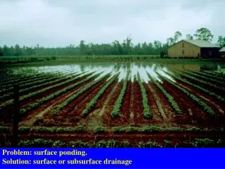
DesignofSurfaceDrainageSystems • Surfacedrainageinvolvestheremovalof excesswater from the surfaceof thesoil. • Thisisdonebyremovinglowspotswherewater accumulatesby landformingorbyexcavating ditchesoracombinationof thetwo.
SurfaceDrainage • Land forming is mechanically changing the land surface todrainsurfacewater. • Thisisdonebysmoothing,grading,beddingorleveling. • Land smoothing is the shaping of the land to a smooth surfacein ordertoeliminateminordifferencesin elevationand thisisaccomplishedby fillingshallow depressions. • Thereisnochangeinlandcontour. Smoothingisdone • usinglandlevelersorplanes
SurfaceDrainageConcluded • Land grading is shaping the land for and drainage done by cutting, filling to planned e.g. smoothening continuous surface grade using bulldozers or scrapers.
DesignofDrainageChannelsorDitches • EstimationofPeakFlows:Thiscanbedone using the Rational formula, Cook's method, Curve Number method, Soil Conservation Service method etc. • Drainagecoefficientsare at times used in the tropics especially in flat areas and where peak stormrunoff would requireexcessivelylarge channels andculverts. • This maynotapplylocally becauseofhigh slopes.
TheRationalFormula: • Itstatesthat: • qp = (CIA)/360 • where qpisthe peakflow (m3/s);Cis dimensionlessrunoff coefficient;Iisthe rainfall intensity for a given return period. Return period is the average number of years within which a given rainfalleventwillbeexpectedtooccur atleast once. • Aistheareaof catchment (ha).
UsingtheRationalMethod • Obtain area of catchment by surveying or from maps or aerial photographs. • Estimate intensity using the curve in Hudson's Field • Engineering. • The runoff coefficient C is a measure of the rain which becomes runoff.On a corrugated iron roof, almost all the rain would runoff so C = 1, while in a well drained soil,nine-tenthsoftherainmaysoakinandsoC= • 0.10.ThetablefromHudson'sFieldEngineeringcan beusedtoobtainCvalue.Wherethecatchmenthas • several different kinds of characteristics, the different values should be combined in proportion to the area of each.
Cook'sMethod • Three factorsareconsidered: • Vegetation • Soilpermeability • Slope. • These are the catchment characteristics. For each catchment, these are assessed and compared with Table3.4of Hudson'sFieldEngineering
Example • Acatchmentmaybe heavygrass(10)on shallowsoilswith impededdrainage(30)and moderateslope(10). • Catchment characteristics (CC) is then the sum ofthethreei.e.5.0 • The areaof the catchment is then measured, and using the Area, A and the CC, the maximum runoff canberead fromTable3.5(Field Engineering,pp.45).
Cook’s MethodContd. • This gives the runoff for a10 yr returnperiod. For otherreturnperiods,theconversionfactoris: • Another factor to be considered is the shape of the • catchment. • Table3.5 gives the runoff for a catchment, which is roughly square or round. For other catchment shapes, thefollowingconversionfactorsshouldbeused: • Square or round catchment (1)Long & narrow (0.8) Broad&short(1.25)
SurfaceDrainageChannels • The drainage channels are normally designed using the Manning formula. The required capacity of a drainage channeliscalculatedfrom thesummationofthe inflowingstreams. • The bed level of an open drain collecting flow from field pipe drains should be such as to allow free fall from the pipedrainoutletsundermaximumflowconditions,with an allowance for siltation and weed growth.300 mm is a reasonablegeneralfigure.
SurfaceDitchArrangements • Theditcharrangementcanberandom,parallelor cross-slope. • Randomditchsystem:Usedwhere only scattered wetlandsrequiredrainage. • Parallel ditch system:Used in flat topography. Ditches areparallelandperpendiculartothe slope. Laterals, which run in the direction of the flow,collectwaterfromditches.
DESIGNOF SUB-SURFACEDRAINAGESYSTEMS • Sub-surfacedrainageistheremoval of excessgroundwaterbelowthesoilsurface. • It aims at increasing the rate at which water will drain from the soil, and so lowering the water table, thus increasing the depth of drier soilabovethewatertable. • Sub-surface drainage can be done by open ditchesorburieddrains.
Sub-SurfaceDrainageUsingDitches • Ditcheshavelowerinitialcostthanburieddrains. • Thereiseaseof inspectionandditchesare applicable in some organic soils where drains are unsuitable. • Ditches,however,reducethelandavailablefor cropping and require more maintenance that drains duetoweedgrowthand erosion.
Sub-SurfaceDrainsUsingBuriedDrains • Buried drains refer to any type of buried conduits having open joints or perforations, which collect andconvey drainagewater. • They canbe fabricatedfromclay,concrete, corrugated plastictubesor anyother suitable material. • The drainscanbe arrangedina parallel, herringbone,doublemainorrandomfashion.
Sub-SurfaceDrainageDesigns • The Major Considerations in Sub-surface DrainageDesignInclude: • DrainageCoefficient • DrainDepthandSpacing • DrainDiametersandGradient • DrainageFilters
DrainageCoefficient • This is the rate of water removal used in drainagedesigntoobtain thedesired protection of crops from excess surface or sub-surfacewaterand can be expressed inmm/day,m/day,etc. • Drainageisdifferent inRain-FedAreas andIrrigatedAreas
DrainageCoefficientinRain-FedAreas • This is chosenfromexperiencedepending on rainfall.Thefollowingareguidelines. • A. Table4.1: DrainageCoefficientforRain-FedAreas* • Meanannualrainfall Drainagecoefficient(mm/day) (mm/yr) • MinistryofAgric. Hudson • ...................................................................................................... • *FromMinistryofAgric.,U.K(1967)&Hudson(1975)
DrainageCoefficientinIrrigatedAreas In irrigated areas, water enters the groundwaterfrom: • Deeppercolation • Leachingrequirement • Seepage • Conveyance losses andcanals from watercourses
Example In the design of an irrigation system, the following propertiesexist:Soilfieldcapacityis 28%by weight, permanent wilting point is 17% by weight; Bulk density = 1.36 g/cm3; root zone depth is 1 m; peak ET is 5 mm/day; irrigation efficiency is 60%, water conveyance efficiency is 80%, 50 % of water lostincanals contributeto seepage;rainfallfor January is 69 mm and evapotranspiration is 100 mm; salinity of irrigation water is 0.80 mmhos/cm whilethatacceptableis4mmhos/cm.Compute thedrainagecoefficient.
Solution: • Readilyavailablemoisture(RAM) = ½(FC-PWP) =1/2(28 • -17)=5.5%. Indepth, • RAM= 0.055x1.36x1000mm= 74.8mm = Netirrigation • Shortest irrigation interval =RAM/peak ET = 74.8/5 =15 days • Withirrigationefficiencyof60%,Grossirrigationrequirement • = 74.8/0.6= 124.7mm. Thisisperirrigation. • (a)Waterlosses=Gross-Netirrigation=124.7-74.8= • 49.9mm • Assuming 70% is deep percolationwhile 30% is wastedon thesoilsurface(Standardassumption),deeppercolation= 0.7x49.9=34.91mm
Solution: (b)Seepage • Seepage = 1/2 x 31.2mm • • = 15.6mm
Solution: = 0.8(100 -69) 4 (c) LeachingReqd. = Ecirrig(ET-Rain) • • • Ecaccep = 7.75mm Thisis foronemonth;for15days,wehave3.88mm • (d) Rainfall= 69mm;for15days,thisis 34.5mm • Note: Insurfaceirrigationsystems,deeppercolationismuchhigher thanleachingrequirementsoonly theformerisusedin computation. • It is assumed that excess water going down the soil as a result of deep percolation can be used for leaching.In sprinkler system, leaching requirement may be greater than deep percolation and can beusedinstead.
SolutionConcluded • NeglectingLeachingRequirement,Totalwater inputintodrains isequalto: • 34.91 + 15.6 + 34.5 = 85.01mm • Thisisper15days,sinceirrigationintervalis15 days • Drainagecoefficient = 85.01/15=5.67 • = 6mm/day.
DrainDepthandSpacing Lisdrainspacing;hismiddrainwatertableheight(m)above drain level; Do is depth of aquifer from drain level to impermeable layer(m); q is the water input rate(m/day) = specific discharge or drainage coefficient; K is hydraulic conductivity(m/day); H is the depthtowatertable.
DesignWatertabledepth(H): • Thisis theminimumdepthbelow the surface at which the water table should be controlledandis determinedbyfarming needsespeciallycroptolerancetowater. • Typically,itvariesfrom0.5to1.5m.
DesignDepthof Drain • Thedeeperadrainisput,thelargerthespacingandthe moreeconomicalthedesignbecomes. • Draindepth, however, isconstrainedbysoil and machinerylimitations. • Table : TypicalDrain Depths(D)
DrainSpacing(L) • Thisis normallydeterminedusing theHooghoudt equation. Hooghoudtequation statesthatforditches reachingthe impermeablelayer: L2 = 8KDoh+ 4Kh q q • (Seedefinitionsoftermsinpreviousslides) • Fortubedrainswhichdonotreachtheimpermeable layer,theequationcanbemodifiedas: • L=8K dh+4Kh2 • q q • WherediscalledtheHoughoudt equivalentd.The equation for tube drains can be solved using trial and errormethodor thegraphicalmethod.
Example Forthedrainagedesignofanirrigatedarea,drainpipes with a radius of 0.1 m are used. They are placed at a depth of 1.8 m below the soil surface. A relatively impermeable soil layer was found at a depth of 6.8 m below the surface. From auger hole tests, the hydraulic conductivity above this layer was estimated as 0.8 m/day. The average irrigation losses, which recharge the groundwater, are 40 mm per 20 dayssotheaveragedischargeof thedrainsystem amountsto2mm/day. Estimatethedrainspacing,ifthedepthofthewatertableis 1.2m.
SolutionContd. • TrialOne • AssumeL=75m,fromHoughoutdtableprovided,with L= 75 m,andDo = 5 m,d =3.49m. L2 • From equation (1), = (1920 x 3.49) + 576 = • 7276.8; L=85.3m • Comment: TheLchosenissmallsince75 < 85.3m • • • TryL= 100 m,fromtable,d =3.78 • From(1), L2 = (1920x 3.78) +576 = 7833.6 ; • L=88.51m • Comment: Since88.51<100,tryasmallerL; Lshould • bebetween75and100m.
AnalyticalSolutionConcluded • TryL= 90m,d =3.49 + 15/25(3.78- 3.49) =3.66m • • = (1920 x 3.66) + 576 = 7603.2m;L=87 m L2 • Comment: Since87<90,tryasmallerL;Lshouldbe between 75and90. • TryL= 87m, d = 3.49 + 12/25(3.78-3.49)=3.63m • • = (1920x 3.63)+ 576 = 7545.6;L = 86.87m L2 • Comment: The difference between the assumedand calculatedLis<1, so: DrainSpacing=87 m.
GraphicalSolution • • • Locatethetwopointsongraphgivenandjoin. • For avalueofDo= 5 m; producedownwardstomeettheline. Read offthespacingonthediagram • L = 87m