Download
1 / 12
130 likes | 428 Views
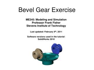
ME345: Modeling and Simulation Professor Frank Fisher Stevens Institute of Technology Last updated: June 25, 2009 Software versions used in the tutorial: SolidWorks 2007 SP4.0. Bevel Gear Exercise. Table of Contents: Part 1: Background Part 2: Preparing the Simulation

E N D
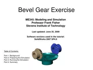
ME345: Modeling and SimulationProfessor Frank FisherStevens Institute of TechnologyLast updated: June 25, 2009Software versions used in the tutorial:SolidWorks 2007 SP4.0 Bevel Gear Exercise Table of Contents: Part 1: Background Part 2: Preparing the Simulation Part 3: Running the Simulation Part 4: Summary
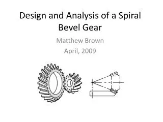
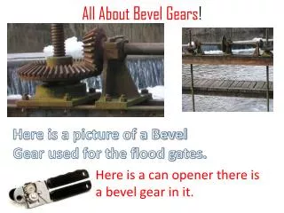
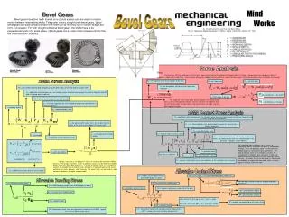
Part 1: Background This analysis is primarily an exploration of the uses for Joint Couplers in COSMOSMotion An explanation of Joint Couplers: Joint couplers allow the motion of a revolute, cylindrical, or translational joint to be coupled to the motion of another revolute, cylindrical or translational joint. The two coupled joints may be of the same or different types; for example, a revolute joint may be coupled to a translational joint. The coupled motion may also be of the same or different type. For example, the rotary motion of a revolute joint may be coupled to the rotary motion of a cylindrical joint, or the translational motion of a translational joint may be coupled to the rotary motion of a cylindrical joint. Coupler joints are used here to produce motion between objects of complex geometry where a simple mate will not suffice. In this case the objects are bevel gears
You will remember from ME 361 (Design of Machine Components) in the sections concerning gear trains that speed ratios between gears can be determined with the equation: Where: n = gear speed N = number of teeth d = pitch diameter Remember to keep in mind that the velocity changes direction between each gear. When applying the joint couplers the most important things to know are: • How the gear ratio will affect the output motion of the connecting gear. This will need to be calculated yourself and entered when defining the joint coupler properties. In this case the calculation is simple as the parts used in the assembly: 20bevel4 and 20bevel5 both contain 20 teeth and the part 40bevel1 contains 40 teeth. • The direction of the output gear velocity relative to that of the input gear. Normally this is as simple as changing the sign of the output motion when defining the joint coupler but you need to be careful what parts you assign as the input and output gears.
Bevel Gear Exercise Part 2: Preparing the Simulation • Open “Bevel_Gears_For_ppt.sldasm” • When asked to “Automatically add new Parts to Grounded or Moving Parts?” Select “No”
Bevel Gear Exercise • Define Moving and Ground Parts (There are no ground parts in this model) Bevel_Gears_For_ppt.sldasm
Select Ground as 2nd Part Select Gear as 1st Part 2 1 Bevel Gear Exercise • Add Revolute Joint Select Edge for Location 3
Bevel Gear Exercise • Add Revolute Joint Select Ground as 2nd Part Select Gear as 1st Part 1 2 Select Edge for Location 3
Select Gear as 1st Part 1 Select Edge for Location 3 Bevel Gear Exercise • Add Revolute Joint Select Ground as 2nd Part 2
Bevel Gear Exercise • Add Joint Motion on 20Bevel5
Bevel Gear Exercise • Add Joint Coupler • Define Joint Coupler between 20Bevel5 and 40 Bevel1 (Joint 1 and Joint 3) • Define Joint Coupler between 40 Bevel1 and 20Bevel4 (Joint 3 and Joint 2) • Enter Values as shown below
Bevel Gear Exercise Part 3: Running Simulation • Press calculator button to run simulation • Set frames to 250
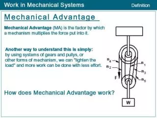
Part 4:Summary Couplers allow the proportional movement of one joint with respect to another. Couplers can link: Rotational - Rotational Rotational - Translational Translational - Translational Available for combinations of Revolute, Cylindrical, and Translational joints One joint can be linked to multiple joints provided they do not conflict with motion generators or other couplers Couplers are primarily used for representing gears without taking into account losses