Download
1 / 35
350 likes | 606 Views
554-556 Third Avenue NY, New York. Michelle L. Mentzer Structural Option. Outline. Building Information Structural Background Problem Statement Proposal Structural Design Architecture Construction Management Conclusions. Design Team. Owner Maidman Development Architect

E N D
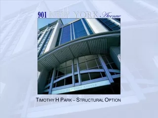
554-556 Third Avenue NY, New York Michelle L. Mentzer Structural Option
Outline • Building Information • Structural Background • Problem Statement • Proposal • Structural Design • Architecture • Construction Management • Conclusions
Design Team • Owner • Maidman Development • Architect • H. Thomas O’Hara Architects • Structural Engineer • DeSimone Consulting Engineers • CM • BrawnMade Construction • Tishman Staff • MEP Engineer • MGJ Associates
Location 37th Street and Third Avenue Midtown Manhattan
Building Information • 30 Stories • 120,000 sq. ft. • 3600 sq. ft. Footprint • Residential occupancy • Ground floor • Retail space • Residential lobby • Fifth floor • Fitness room • Living units Ground Floor Fifth Floor
Building Information • Residential occupancy • Floors 2-24 • Marriott ExecuStay Suites • Floors 25-30 • Double height condominiums Floor 8-24 Floor 25-30
Structural Background Gravity System • Flat plate concrete construction • Floors 6-30 cantilever over buildings on 2 sides • Flat plate supports cladding load at cantilevers • Column walks shift loads toward building interior • Post-tensioning in slabs and columns near walks • Mat Foundation
Structural Background Column Walk • Column 12 on floor 5 • Column 18 on floor 8 • Resembles a wall between levels
Structural Background Lateral System • Wind loads govern for design loads • Shear wall core • Relatively uniform throughout building • Link beams connect walls above door openings • Extends above main roof to enclose penthouse
Problem Statement • Architectural style limited by thin cantilever slabs that cannot support heavy cladding • ADOSS model proved slabs would fail with heavy cladding load • Metal panels are the only option
Proposal • Develop an additional support system capable of carrying excess cladding loads • Steel trusses at roof level • Tension members hanging from trusses carry loads • Change façade through architectural precast panels and roof trusses • Determine impact these changes have on construction schedule, site layout and cost
Structural Design Truss Design • Braced frames replace shear walls above roof • System modeled in RISA • Applicable load cases considered • Continuous top & bottom chords • Pins at all other locations • Fixed supports at columns and shear walls
Structural Design Supporting Columns • Located wherever a truss joint coincides with a column/shear wall • Connections not necessarily centered on column
Structural Design Truss and Braced Frame Member Sizes • Maximum consistency • Lightest weight sections where possible • All wide flange shapes W14x90 W21x83 W14x211
Structural Design Truss Connections • Heavy bracing type connections at truss joints • Base plate and anchor bolts connect bottom chord to columns or shear walls
Structural Design Tension Members • W14x22, W14x34, W14x68 • Largest members at top • Reduce size as allowable • Hanger connection • Tension splices where necessary
Structural Design Slabs • No gravity load transferred from cladding to slabs • Cladding directly supported by columns • Angles welded to column flanges and bolted to panels • Lateral ties from panels to slab • Transfer wind forces to rigid diaphragm
Structural Design Column Walk • Added compression in column creates more tension in slab near column 18 on level 8 • Initially gravity load is fully vertical • As core reinforcement in column slants, gravity force creates horizontal component at slab level • Horizontal tension at level 8 is resisted by post-tensioning • One additional 1 3/8 “ Dywidag in level 8 slab • Original design calls for 5 Dywidags
Structural Design Column Capacities • Column capacities checked at critical locations using PCA Column • All support columns checked for gravity loads and moments from eccentricity • Dimensions and reinforcement increase in some areas • Exterior columns not supporting truss also checked • Supporting extra loads directly from cladding • Sufficient as designed to carry cladding loads
Structural Design Tension in Columns • Created by moment from cantilevered truss • Resisted by reinforcement in concrete
Structural Design Shear in Columns • Lateral loads from trusses and braced frames transferred directly to columns at roof level • Rigid diaphragm redistributes load at floor thirty • Where columns are in tension, shear reinforcement takes full shear load • Several columns require additional shear reinforcement at roof level
Structural Design Adjusted Column Sizes
Structural Design Overturning Moments • 0.9D+1.6W load case critical • Overturning caused by combination of wind and truss forces • Building overturning resisted by self weight and foundation • Safety factor (critical case)=2.5 • Moments cause tension and compression in opposite flanges of shear wall core • Spreadsheets used to check reinforcement for tension and compression in shear walls • Sufficient as designed to resist tension and compression loads
Architecture Cladding • Precast architectural panels • Architectural Precast Association • Acid-etched medium with yellow pigment • Red and beige tones blend with surroundings • Hint of yellow sets it apart and ties in idea of light associated with the name “Aurora”
Architecture Truss Design • Similar truss idea used in IBM Building, Baltimore, MD • Shape of trusses emphasizes cantilevers • Maximum symmetry possible • Add interest and detract from tall slender penthouse • Visible from street level
Architecture Column Dimensions Changes • West window shifts • No other substantial changes to layout necessary
Architecture Before After
Construction Management Sequencing • Finish pouring concrete before erecting steel • Enclosures cannot begin until after steel work is complete • Crane only needed for one task at a time
Construction Management • Tower crane capacity = 8 tons • Maximum member weight = 5 tons • Maximum panel weight = 7.5 tons • Street parking behind crane Site Logistics
Construction Management Schedule Impact • Durations from MC2 • Steel adds approx. 1.5 months to schedule • Panels take about the same amount of time to hang • Overall extension of schedule = 1.5 months
Construction Management Cost • Initial overall cost • R.S. Means = $18.2 million • Structural steel • MC2 =$220,000 • Panels (MC2) • Metal panels = $960,000 • Architectural precast panels = $2,200,000 • Proposal adds $1.5 million or 8.6% of initial cost
Conclusions • Trusses add architectural interest and allow use of a heavier cladding system • No substantial interruptions to interior layout • $1.5 million cost increase • 1.5 month schedule increase
Conclusions Recommendation • Revenue from architectural enhancements will not likely offset added costs and schedule delays • Use original metal panel cladding system
Acknowledgements DeSimone Consulting Engineers Penn State AE Faculty AE Class of 2003 My Family