1 / 17

Citation Generator

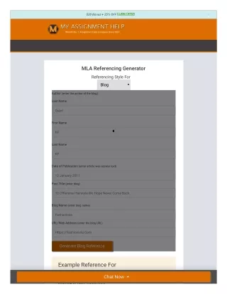
Our Citation Generator is an easy-to-use tool designed to create accurate and properly formatted citations for academic, professional, or research writing. By inputting key details about a sourceu2014such as the author, title, publication year, and URLu2014it instantly produces citations in various styles, including APA, MLA, Chicago, and Harvard. Whether you're working on a paper, thesis, or project, a citation generator saves time, ensures accuracy, and helps you avoid plagiarism. Many tools also support in-text citations, bibliographies, and source organization, making them essential for students,

Maheswari7
Download Presentation

Citation Generator

An Image/Link below is provided (as is) to download presentation Download Policy: Content on the Website is provided to you AS IS for your information and personal use and may not be sold / licensed / shared on other websites without getting consent from its author. Content is provided to you AS IS for your information and personal use only. Download presentation by click this link. While downloading, if for some reason you are not able to download a presentation, the publisher may have deleted the file from their server. During download, if you can't get a presentation, the file might be deleted by the publisher.

E N D

Presentation Transcript


  1. of Science and Technology ISSN: 2456-5660 Volume 6, Issue 05 (SEP-OCT 2021) Journal www.jst.org.in DOI:https://doi.org/10.46243/jst.2021.v6.i05.pp159-176 A REVIEW OF RECENT DEVELOPMENT IN PARAMETRIC BASED ACOUSTIC EMISSION TECHNIQUES APPLIED TO CONCRETE STRUCTURES Dr.Mohammed Ahmed Hussain1 , Shaik Mohammed Javid2 Professor1 , Assistant professor2 Department Of Civil Enginnering NAWAB SHAH ALAM KHAN COLLEGE OF ENGINNERING & TECHNOLOGY NEW MALAKPET , HYDERABAD-500 024 Abstract In this post, we'll take a look at some of the most recent advancements in parametric AE approaches for concrete buildings. AE testing of concrete buildings has made major advancements over the years, incorporating a variety of methodologies and models that have been established by earlier researchers. To provide a general overview of the distinctive aspects of parametric AE approaches for concrete buildings that have been used throughout time. Traditional parameter-based AE approaches for concrete buildings are emphasised. There has already been a substantial quantity of study published on the use of AE methods on concrete structures, and this research has received a great deal of attention. Recent research on concrete bridge beam damage, such as AE energy analysis and b-value analysis, have also been addressed. Concrete beam specimens were fractured and the AE energy emitted throughout the process were summarised. AE properties of concrete have been studied extensively during the last three decades. We hope that this overview of parametric AE techniques for concrete structures will assist researchers and engineers better understand concrete failure mechanisms and devise new methodologies for structural diagnostic inspection and concrete structure failure prediction/prevention. Keywords: structural damage evaluation using b-value analysis in conjunction with the use of methods for acoustic emission Introduction This novel, non-invasive and passive nondestructive testing (NDT) approach is called acoustic emission monitoring. Transient elastic waves (ultrasonic frequency range) are created by the fast release of energy from a localised source inside a material [1–9]. AE is classified as a phenomenon. Deformation processes like as crack development and plastic deformation are the primary causes of AE. As long as the elastic waves are of sufficient amplitude, they may be detected by transducers (sensors) connected to the specimen's surface [5,10]. Materials fracture may be monitored with great precision using the AE method. Localized strain energy is generated when fractures form in a material. Sensors are used to monitor the energy emitted by fractures as they expand. Actually, AE testing is a way for determining whether or not there is any activity associated with an electroencephalogram (EEG) (also known as electroencephalography, or EEG). Monitoring the structural health of buildings and bridges is a common use for the AE approach [8,9,11–16]. Figure 1 illustrates the usual characteristics of an AE signal. The AE technique's benefits include the ability to pinpoint the exact location of growing cracks and the ability to test the whole structure at once without interfering with any of the structure's processes. Time differences between AE signals received by various AE sensors reveal the presence of AE. It is possible to determine the kind of fracture and its orientation using moment tensor components and AE's b-value analysis [9,17 – 22]. For the most part, researchers use two basic approaches to AE techniques: the classical or parameter-based method and the quantitative or signal-based approach [9,22]. Both methods are used by civil engineers working in the concrete constructions field. Using signal-based Published by: Longman Publishers www.jst.org.in

  2. of Science and Technology ISSN: 2456-5660 Volume 6, Issue 05 (SEP-OCT 2021) Journal www.jst.org.in DOI:https://doi.org/10.46243/jst.2021.v6.i05.pp159-176 approaches to monitor huge buildings is currently not practicable [22]. It is possible to better identify the source of AE by measuring signal characteristics such as maximum amplitude, peak duration and frequency as well as by measuring signal phase and frequency spectra. It is necessary to analyse AE signal properties such as peak to peak and rise to decay times as well as energy and frequency content in this study. The AE event's origin may be determined using these signal characteristics [9,23]. 2. Early AE studies of concrete The first AE tests were performed in the middle of the 20th century [2,4]. Kishinouye [8,24–28] was the first to report on the AE experiment. A dissertation by Kaiser, published in 1953, was the first in Germany to present the AE phenomena known as the "Kaiser effect" [143]. Until the prior maximum applied load is surpassed, there is no observable AE in the Kaiser effect. A pioneering article on acoustic emission under applied stress was written by Schofield [29] in 1954, and he was the first to use the phrase "acoustic emission." An in-depth explanation of AE testing may be found in the ASNT's NDT handbook [5]. When Ohtsu (Grosse and Ohtsu 2008) evaluated the use of AE testing in civil engineering, he focused mostly on concrete structures [9]. Recent developments in AE monitoring and recording systems Since its inception in 1968, Dunegan has been the world's oldest maker of AE equipment. It is a prominent firm and supplier of technology-enabled asset protection solutions for industrial, public, and private infrastructure that employ acoustic signals to analyse the structural integrity. Members of the Physical Acoustics CorporationMISTRAS Group, Inc., is actively working on AE sensors and AE measuring devices in research, design, and fabrication. As far back as 1978, PAC has been manufacturing a comprehensive variety of commercially accessible AE devices. For more than 25 years, VallenSysteme GmbH has manufactured AE testing equipment. Equipment for AE testing development and production is the only focus of VallenSysteme GmbH. Digital testing systems were launched in 1986 and 32-bit Windows-based software in 1998 by the company Vallen AE systems, which provided the most sophisticated technology at the time. Both in the lab and in the field, Vallen AE systems have shown their worth. Some researchers may have built their own AE systems and utilised them for research purposes. The specifics of these systems are seldom made public. Some research institutions in Japan, Russia, China, Germany, the United States and Switzerland have built their own AE systems to meet their specific needs [5,9], and this should be emphasised. 4. Significance of AE parameters and their applications 4.1 Analysis of AE energy released during concrete fracture Published by: Longman Publishers www.jst.org.in

  3. of Science and Technology ISSN: 2456-5660 Volume 6, Issue 05 (SEP-OCT 2021) Journal www.jst.org.in DOI:https://doi.org/10.46243/jst.2021.v6.i05.pp159-176 When discussing AE energy in general, the rectified AE signal is considered. The entire elastic energy released by an AE event is referred to as AE energy. Elastic waves are formed and transmitted in all directions as an AE event takes place at a source and eventually reach the material's surface. Some studies have employed AE signal root mean square values. Attenuation owing to material medium, coupling medium, and distance from source all impact strain energy release [32–36]. The following is a definition of AE energy: [5] For example, where Vi is the voltage transient of an ith channel at ith channel t0 and t1 are the start and end times of a voltage transient recording, respectively We rely on the energy count data provided by the testing equipment in our job. Observed signal envelop energy is supplied in terms of a count of the measured signal area. Absolute energy levels in joules are now attainable from commercially available technology. This is the case today. It was found that the AE energy might be utilised to monitor the structural state of concrete bridge beams by Colombo et al. [37,38]. Relativity ratio (ratio of average energy during unloading phase to average energy during loading period) was developed by researchers to analyse the damage condition of concrete structures using AE energy. AE contrasted these findings with those from a previous research using the NDIS: 2421- method for in-situ concrete structure monitoring. It was thus established that concrete buildings may be assessed for damage using AE energy [9,37 – 39]. 4.2 Use of AE amplitude to compute AE-based b-value In concrete structures, amplitude is one of the most essential AE metrics that researchers use to evaluate damage. Damage assessment in concrete structures relies on the use of b-Value, one of the most essential metrics. By using amplitude distribution data from seismology [21,23,40], b-value changes schematically at different stages of fracture in concrete structures as depicted in Figure 2 [21,23,40]. (Top) and (Bottom) channels 3 and 7 b-value variations during the course of the experiment are shown in Figure 2. The arrows on the vertical lines depict the various phases of cracking [21]. 4.3 Use of AE hit rate in assessing nucleation of crack growth Published by: Longman Publishers www.jst.org.in

  4. of Science and Technology ISSN: 2456-5660 Volume 6, Issue 05 (SEP-OCT 2021) Journal www.jst.org.in DOI:https://doi.org/10.46243/jst.2021.v6.i05.pp159-176 Studies on microcracking in concrete structures' nucleation stages have used AE hit as a criterion. Reinforced concrete (RC) beams exposed to corrosion of steel reinforcement were studied by Yoon et al. [41]. Figure 3 shows a plot of cumulative impacts over time under cyclic load, and it can be seen that the AE count decreases as corrosion severity increases. An AE test may also be performed to determine the extent of corrosion on RC beams [41]. If you're looking to understand how microcracks and macrocracks form in quasi-brittle materials, Rao et al. [42] may help. The creation of microcracks causes AE activity to continuously and slowly rise. This has led to the usage of AE hit as a parameter in the analysis. Figure 3: RC beam AE hit totals over time (in seconds) (41); Applied aesthetic. Cyclic loading on reinforced concrete beams with varied levels of reinforcement has resulted in documented AE impacts that vary, as illustrated in Figure 4. 4.4 Application of count rate to assess damage in concrete The count rate is defined as the number of times a signal passes a certain threshold within a given period of time [5]. Additionally, the AE count rate may be used to estimate the strength of an AE event. According to one author, because an AE hit or count rate cannot accurately evaluate damage, the circumstances under which AE activity increases should be considered [43]. An under-reinforced beam sliding between reinforcement and concrete was shown to have an exponentially increasing AE count rate. An over-reinforced beam's count rate, in contrast, was consistent all the way up to eventual collapse [43]. Many researches have proven that AE count is also an essential parameter. 4.5 Field investigations Casa Capello, an antique Italian structure, was assessed by Carpinteri and Lacidogna (2003; 2006) with the use of AE testing. According to this study, the propagation of fractures was shown to slow down as the number of cumulative AE occurrences increased [77,78]. Yuyama et al. (1998) monitored an old dock under mobile loading conditions for acoustic emissions (AE). When loading and unloading, they discovered that the first cycle had less AE hits compared to the second and third cycles, which had more Published by: Longman Publishers www.jst.org.in

  5. of Science and Technology ISSN: 2456-5660 Volume 6, Issue 05 (SEP-OCT 2021) Journal www.jst.org.in DOI:https://doi.org/10.46243/jst.2021.v6.i05.pp159-176 AE hits than the first cycle. While loading and unloading, the Kaiser effect was quite prominent in the second scenario. The loading and unloading stages of the third cycle [43,138] showed no Kaiser effect. 5. AE research work on concrete Nielsen and Griffith [44] and Niwa et al. [45] examined the AE of plain concrete. When compressive loads were applied to concrete, researchers noticed a distinct sound, which they dubbed the 'Kaiser effect' in engineering materials [9]. Up to a 75 percent load, the Kaiser effect was found. Figure 4 shows AE impacts on the RC beam when incremental cyclic loading is applied [43]. The behaviour of AE signals has been shown to be strongly connected to volumetric change in many studies [9,46,47]. The relationship between the increase in Poisson's ratio and the increase in AE production in concrete under compressive stress has been summarised [48]. For nondestructive examination of concrete buildings, Drouillard suggested the use of AE testing in the late '70s [49,50]. A thorough history of AE was also described by Drouillard [51]. Under uniaxial compressive force, researchers investigated the connection between the fracture process and concrete's volumetric change. There were AE events even during the unloading process, and the formation of AE was shown to be tightly linked to the volume change in specimens, according to Robinson [52]. For RC structures, Vogel and Koppel [53] addressed the limits of AE analysis. When Poisson's ratio and axial strain are raised, the wave velocity in concrete falls based on the AE activities observed [48]. Green and Dunegan [51] based their standard processes and gadgets on Schofield's research. Crack types were categorised using the combination of 'average frequency (counts/duration) and rising time/amplitude' after a thorough investigation of concrete. [54] AE from RC beams has also been examined by Lim and Koo [55] and Kobayashi et al. [56]. The corrosion of reinforcing steel in RC beams was studied using AE monitoring [41,57,58]. Reinforcing steel corrosion had a significant impact on the rate of AE events and how they were generated [41]. In order to estimate the degree of corrosion-induced damage in RC structures, the total number of AE events decreases as corrosion severity rises [41]. The AE activity of RC beams exposed to a salty environment was regularly evaluated for three years [59–61]. Corrosion cracks in existing buildings were detected using continuous AE monitoring [62]. AE activity and half-cell potentials were studied in an experimental manner. Two very active phases of AE impacts were discovered during the accelerated corrosion test [61]. It is consistent with the salt attack degrading process that these two phases are present. Moment tensor analysis was used to pinpoint concrete cracking processes in a simulation of crack propagation caused by corrosion of reinforcing steel bar [17,64]. (Ohtsu 1984). There are several ways to find out the direction and slip vector of an AE source's crack, but one approach that is very beneficial is moment tensor inversion. The tensor components of a moment tensor are found by measuring the amplitude of a p-wave. Full-space green function of homogenous and isotropic materials Published by: Longman Publishers www.jst.org.in

  6. of Science and Technology ISSN: 2456-5660 Volume 6, Issue 05 (SEP-OCT 2021) Journal www.jst.org.in DOI:https://doi.org/10.46243/jst.2021.v6.i05.pp159-176 has been used to choose the p-wave [19,47]. Tensile fractures are classified as such by using the breakdown of the moment tensor eigen values, whereas shear cracks are classified as such by using the eigen vector eigenvectors. It is possible to get quantitative information on crack nucleation using the SiGMA approach with post analysis [9,22]. Steel fibre RC was studied by Soulioti et al. [66] under bending. The effect of steel fibre content on fracture behaviour and AE was studied using a variety of steel fibre contents. As demonstrated in Figures 5 and 6, the AE activity in concrete was found to be directly related to the fibre content. A research by Yoon et al. [41] used corroded RC beam specimens under bending to characterise and identify several damage mechanisms, such as microcrack formation, localised crack propagation, and debonding of the reinforcing steel. [41]. Reinforcing steel corrosion has been found to have an effect on the occurrence of AE events and on the formation of AEs, as illustrated in Figure 3. Different damage processes were separated and characterised as illustrated in Figure 7 [41] by examining plain, notched-plain, RC beam specimens. 5.1 Characterisation and evaluation of concrete Stress, bearing characteristics, fatigue, and fracture may be characterised through AE testing. AE characterization of concrete and RC structures was examined by Nesvijski [67]. The commencement and propagation of fractures in hard concrete may result in acoustic emissions (AE). Signatures for various phases of concrete life and service are analysed. Quantitative AE analysis models were re-examined. It was found that AE activities and failure mechanisms in RC beams were evaluated during bending and shear failure [43]. For RC beam damage assessment experiments, Yoon et al. [41] used electromagnetic energy (AE). Figure 7 depicts the relationship between AE signal amplitude and signal duration for plain and notched unreinforced concrete beams. The black diamond symbol represents AE events in notched specimens, while the hollow circle symbol depicts AE events in unnotched specimens. It was discovered that AE signals with short duration and low amplitude appeared at various stages of loading, indicating microcracking and the formation of localised cracks. According to the findings, unreinforced concrete Published by: Longman Publishers www.jst.org.in

  7. of Science and Technology ISSN: 2456-5660 Volume 6, Issue 05 (SEP-OCT 2021) Journal www.jst.org.in DOI:https://doi.org/10.46243/jst.2021.v6.i05.pp159-176 beams are more susceptible to microcracks and localised crack propagation under low-load conditions [41,68]. Indicated in Figure 6. For (a) the total number of AE hits and (b) the toughness versus AE hits for fibre content, see (a) and (b). [66] 5.2 Detection and assessment of damage in concrete using AE testing Ohtsu and Watanabe Damage to a structure's AE activity may be evaluated quantitatively using the rate process analysis, which was developed by [69,70]. A concrete specimen with a significant number of microcracks is likely to have an increase in AEs when subjected to stress. AE activity, on the other hand, is steady and modest until ultimate failure in well compacted and fully cured concrete [9]. This occurrence of AE activity under loading was represented as a hyperbolic function in the rate process theory [70]. an ebn is an empirical coefficient and C is the integration constant, and the link between the total number of AE events "N" and the stress level "V(percent)" has therefore been presented as N 14 CV an ebn ; 2. By analysing AE signals, researchers were able to learn about damage processes. In order to evaluate concrete structure damage, AE b-Value analysis is used. The b-value analysis of AE has made it feasible to identify and distinguish between macro and microcracks in a structure [21,142]. An earthquake frequency log-linear plot's negative gradient is called the b-value [9, 21.23.40.74]. [36] Researchers studied stresses in concrete and steel at various phases of loading or damage to determine the b-value [36]. [36] The AE method's Gutenberg–Richter connection between frequency and magnitude is provided by log10NM 14 a 2 b AdB 20; 3 where AdB is the peak AE event amplitude in decibels, bAE is the AE-based b-value, and N(M) is the number of magnitude $M AE hits (or events). A number of studies have been done on the use of b-values in the diagnosis of damaged concrete structures and masonry buildings [73,75–83]. Steel Published by: Longman Publishers www.jst.org.in

  8. of Science and Technology ISSN: 2456-5660 Volume 6, Issue 05 (SEP-OCT 2021) Journal www.jst.org.in DOI:https://doi.org/10.46243/jst.2021.v6.i05.pp159-176 80 70 60 50 40 30 0 500 1000 1500 2000 Vidya Sagar [36] sought to link b-values with steel stresses Time (seconds) Notched 2500 3000 3500 4000 Unreinforced Amplitude Unreinforced beam (notched and plain) AE signals are plotted in Figure 7 [41]. 54 Both B.K.R. Prasad and R.V. Sagar At 03:02 a.m. on September 18, 2013, the [Indian Institute of Science] downloaded the file. According to Colombo et al. [21], bigger b-values in concrete structures indicate more damage due to tiny cracks, whereas lower b- values imply more damage due to macrocracking, as illustrated in Figure 2. 5.2.2 Improved b-value analysis A better b-value (Ib-value) has been suggested as an alternative to the standard b-value for use in AE on concrete and rock [141]. AE signal peak amplitude distributions are characterised by the Ib-value, which is a slope of the Ib-value. The statistical values of the AE amplitude distribution were taken into account while calculating the Ib-value since it was known that the AE amplitude values change over time [40,84]. According to Ib, the value of Ib is known. A1 and A2 are user-defined constants that would represent coefficients of the lower and higher boundaries of the amplitude range in order to produce a correct straight line with a mean amplitude of s. Shiotani et al. [85,86] investigated the Ib-value analysis of AE for damage assessment in concrete buildings. [21,86] Non-quantitative findings might occur because of the different monitoring circumstances in each application (Ohtsu and Gross 2008). Monitored situations do not alter the Ib- value, which is unique to each damage level. A study by Shiotani et al. [85] used the Ib-value to determine the extent of damage to concrete piers after an earthquake. The Ib-value was computed based on the AE events that occurred on the pier, and this value was used to determine the degree of damage. 5.3 Micromechanics of fracture in concrete Assuming that aggregates are spherical in form, researchers previously constructed a computational model for fracture processes in concrete at the microscale [87–95]. Computer tomography (CT-scan) has recently been used to simulate the aggregates in a similar way. The aggregates' form isn't entirely spherical, but it's the closest thing we have to a sphere. A lattice model has been utilised by researchers in recent years to simulate a broad variety of studies relevant to the fracture process in concrete [96]. In most cases, however, only the load–displacement diagram and the macroscopic fracture pattern have been compared between computational and experimental data [96]. Comparing the lattice model's capacity to forecast the emergence of microcracks in both the pre-peak and post-peak regimes with that of AE observations would be very valuable. The applicability of the lattice model to concrete fracture was investigated by Vidya Sagar et al. [97] utilising AE testing. Testing was carried out using three-point bend (TPB) specimens that had been notch notched (CMOD). A triangular two-dimensional (2D) lattice network of beam components was used to model the full fracture process throughout the predicted fracture process zone (FPZ) width. A coarse triangular finite element mesh was used to discretise the remainder of the beam specimens.. Concrete's discrete grain structure was produced based on the spherical grain assumption. In general, the load-CMOD charts produced by the simulations matched the experimental data rather well. The simultaneous monitoring of AE release occurred throughout the experiment [97]. The writers employed PAC's 8-channel AE system. SAMOSAE win is the programme in use. Resonant transducers (R6D AE transducers) were employed since their sensitivity peaked at 50 kHz. Published by: Longman Publishers www.jst.org.in

  9. of Science and Technology ISSN: 2456-5660 Volume 6, Issue 05 (SEP-OCT 2021) Journal www.jst.org.in DOI:https://doi.org/10.46243/jst.2021.v6.i05.pp159-176 Nondestructive Testing and Evaluation (NDE) Sensor Diameter Its diameter was 19 millimetres, and its height was 22.0 millimetres, making it suitable for temperatures ranging from 265 to 1778 degrees Celsius. The AE transducers have a maximum sensitivity of 75 dB. They are very sensitive. The frequency ranged from 35 kHz to 100 kHz. An AE impact was recorded and compared to the number of cracked lattice components that occurred during the test. To better understand when microcracks begin to occur in the pre-peak and post-peak regimes, the cumulative AE hits correlated well with the cumulative cracked lattice components presented in Table 1, at all stress levels. For the investigation of the fracture process in concrete, Vidya Sagar and colleagues (2010) determined that the lattice modelling approach is excellently suitable [97]. The lattice network's number of broken beam components was compared to any AE measurements made at a certain load level. In the lattice fracture simulation, the trend in the number of shattered beam elements mirrored the number of documented AE strikes. 5.4 Structural health monitoring using AE testing Using the Kaiser effect, researchers developed the 'felicity ratio' to quantify the damage to concrete buildings [43,98,99]. [ The Kaiser effect is only effective as long as the materials are in the stable domain [9,98], thus the need for its introduction. In other words, AE activity was only found at stress levels lower than the maximum stress that the structure could withstand, as shown in the figure. In order to measure a person's level of happiness, the Felicity Ratio is calculated by dividing sAE by s1st, which is the highest stress level. In a stable state, researchers found that the felicity ratio was $1, but in a damaged or unstable state, the ratio was,1 [43]. Damage assessment and in-situ monitoring of concrete structures using concepts like the felicity ratio have been implemented by AE [39]. AE activity is measured as a 'load ratio,' which is the difference between the structure's highest load during the preceding load cycle and the load at the commencement of AE activity [43]. At the beginning of AE activity, AE characteristics may be used to calculate the load ratio, which is distinct from the felicity ratio. Figure 8 [43] shows a typical AE data categorization based on the load ratio and calm ratio. Published by: Longman Publishers www.jst.org.in

  10. of Science and Technology ISSN: 2456-5660 Volume 6, Issue 05 (SEP-OCT 2021) Journal www.jst.org.in DOI:https://doi.org/10.46243/jst.2021.v6.i05.pp159-176 Figure 8. Classification of AE data by the load ratio and calm ratio [39,43] Because of the difficulty in estimating a structure's maximum stress, the load ratio is not always appropriate for in-situ monitoring of concrete structures [100]. It has been suggested to use the RTRI ratio (ratio of Repeated Train Load at the beginning of AE activity to Relative Maximum Load for Inspection period) as a way to measure how much the AE parameter has fluctuated from the beginning. Any stress/load, strain/deformation, and RTRI ratio measurements may be used to assess when AE activity begins. Even before they are loaded, concrete constructions include defects such as pores, air spaces, and shrinkage fractures. External stress causes the faults, particularly the minor fractures, to expand steadily. It is the combination of microcracks and existing or new microcracks that causes the collapse of the structure. Tension fracture nucleation results in crack opening, while shear crack nucleation is caused by sliding on an existing crack [102,103]. As a general rule, primary AE activity occurs when cracks or fractures are present, while secondary AE activity occurs when the cracks or fractures are absent [9]. Concrete constructions are known to have faults, such as pores, air spaces, and shrinkage fractures, even before they are put to the test. When subjected to external stress, the little fractures expand steadily. In order for the structure to come tumbling down, the microcracks combine with other either existing or freshly produced microcracks. Mode I is present when the fracture development stage is stable. Cracking behaviour in concrete was correlated with the AE parameters by considering two typical forms of mode I and mode II cracking. According to [101], the development of fracture is accompanied by a shift away from tensile to shear-type fracture modes of cracking in concrete structures. When mode I cracks are nucleated, crack opening is the primary motion. To develop mode II cracks, a main action is to slide on an existing fracture. Primary AE activity is often defined as AE activity that is accompanied by crack growth or fracture formation [9]. Secondary AE activity occurs when there is AE activity but no crack propagation. Mode I cracks and AE activity are common in the stable phase of fracture propagation. There will be few AE occurrences as a consequence of the unloading. Mode II fractures may form when AE activity increases towards the point of eventual collapse. As a result, damage might be shown by AE activity when unloading [9]. Tensile cracks accompany AE activity in the steady condition of fracture progression. Because of this, only a few AE incidents are predicted during unloading. Shear fractures may form during the unloading process when the concrete structure is approaching collapse, and hence AE activity during the unloading process has Published by: Longman Publishers www.jst.org.in

  11. of Science and Technology ISSN: 2456-5660 Volume 6, Issue 05 (SEP-OCT 2021) Journal www.jst.org.in DOI:https://doi.org/10.46243/jst.2021.v6.i05.pp159-176 the ability to reveal the extent of damage [9,104]. Thus, the 'calm ratio' is defined as the ratio of cumulative AE activity during the unloading phase to the total AE activity over the whole loading operation. The calm ratio is clearly a sign of instability in the underlying structure. Using the Kaiser effect's load and calm ratios, a technique is provided for evaluating the damage levels in RC beams exposed to recurrent or active traffic loads. It's possible to monitor structural health and the deteriorating process using this approach [37,43,105]. Existing structures or local members are monitored using inspection techniques based on regulations and standards. For example, NDIS-2421 [39] and JCMS-IIIB5706 [54] are built on concrete. Concrete constructions should be monitored in-situ by AE, according to suggested practise [39]. RC beams damaged by gradual cyclic stress are tested to see whether this method is feasible. Figure 9 depicts two different kinds of RC failure mechanisms and the related AE actions. When the beam is bent, bending fractures form in the bending span, eventually leading to failure [96,101,106]. In addition, diagonal shear fractures are formed as a result of shear. A bending failure and a shear failure mode [43] span at failure are shown in Figure 9 together with AE activities and failure types. Sliding between reinforcement and concrete is noticed in the event of an under-reinforced beam because of the yielding of the reinforcement. It is because of this that the Published by: Longman Publishers www.jst.org.in

  12. of Science and Technology ISSN: 2456-5660 Volume 6, Issue 05 (SEP-OCT 2021) Journal www.jst.org.in DOI:https://doi.org/10.46243/jst.2021.v6.i05.pp159-176 frequency of AE grows inexorably. Reinforcement in an over-reinforced specimen, on the other hand, does not show this phenomena, and so AE events are seen at constant rate until the ultimate collapse, and these findings reveal the possibility for prediction of failure in reinforced concrete (RC) beams by means of AE testing. Rossi et al. [115,116] used AE testing to pinpoint the exact physical processes at play during concrete fracture in their experiments. Local structural instability has been shown to affect the occurrence of AE occurrences. Concrete constructions that haven't been destroyed are theoretically stable and have a high degree of redundancy. The Kaiser effect is tightly linked to structural stability, hence AE activity is minimal in a stable structure [9,117 – 119]. Researchers have undertaken extensive research into concrete damage characterization by AE testing [120]. Fracture mechanics research Use of AE testing to measure the FPZ size in concrete When concrete softens, the notion of FPZ was established. [121]. Front and centre (FPZ) is where the crack (notch) in the concrete meets the wall. It was found that Otsuka and Date [122–125] correlated aggregate size with the FPZ's area, taking into consideration the specimen's size. The breadth of the FPZ grows with the size of the aggregate when comparing specimens of the same size. Further research shows that the FPZ duration reduces as aggregate size increases [121 – 123,126–128]. The influence of aggregate on the fracture behaviour of high-strength concrete has also been studied via AE testing [129 – 131]. Increases in specimen size resulted in an increase in the length of the maximum aggregate size, as well. Although many of these events had minor energies, they were found to be concentrated near the notch tip as seen in Figure 10 (see below). The FPZ is defined as the area of AE events that had more than 95% of the total energy. The impact of specimen and aggregate size on FPZ was thoroughly investigated by Ohtsuka et al. in their excellent work. Loading was done using a universal testing equipment. At a rate of 0.005 mm of crack-opening displacement per minute, the specimen was loaded in tension. Locating AE occurrences was done by placing the AE sensors in 3D. Sensors, preamplifiers, a local processor, a digital data recorder and an AE analyzer were all part of the system. There was a 70-dB boost applied to all sensors' resonance frequencies of 140 kHz. The concrete's P-wave velocity was set at 3600 m/s [122]. High-strength concrete TPB specimen was studied by Vidya Sagar and Raghu Prasad [125] to determine the magnitude of the FPZ. When a TPB specimen is used, the fracture process is more accurately modelled. There were fewer high-energy AE occurrences, which are shown in Figure 11 to be localised towards the fracture tip. As seen in Figure 10, the investigation found that the TPB concrete specimen had an FPZ region of roughly 93 percent of the total energy [122,125].6.2 Experiments to relate AE energy and fracture energy of concrete Published by: Longman Publishers www.jst.org.in

  13. of Science and Technology ISSN: 2456-5660 Volume 6, Issue 05 (SEP-OCT 2021) Journal www.jst.org.in DOI:https://doi.org/10.46243/jst.2021.v6.i05.pp159-176 Figure 10 shows the distribution of AE energy in TPB concrete specimens of various sizes (depths of 14 320 mm, 160 mm, and 80 mm, respectively) [125]. a controlled-environment laboratory instrument for studying concrete structure deterioration rather than a field method. When it comes to measuring fracture density, it was previously impossible, but AE has the ability to do so. Studying the link between AE and concrete fracture energy has been done [34,132–133]. It may be shown in Figure 12 that Published by: Longman Publishers www.jst.org.in

  14. of Science and Technology ISSN: 2456-5660 Volume 6, Issue 05 (SEP-OCT 2021) Journal www.jst.org.in DOI:https://doi.org/10.46243/jst.2021.v6.i05.pp159-176 In this diagram, the four energy stages (depth 14 320 mm; a0/d 14 0.15 mm) depict the different places where the AE sources are located. Releasing "AE energy" as a function of "load." Figure 12 shows that the release of 'AE energy' begins only when the peak load is reached [36]. Concrete and cement mortar fracture energies are shown in Figure 13(a)–(c) based on cumulative AE energy. Scattering is more visible in 'AE energy' (Figure 13(b),(c) plots, because AE energy is more localised than fracture energy, which is more global in nature. A larger risk of scattering occurs when the wavelength of a wave is less than the aggregate's size. The AE wave may be further attenuated as a result of this dispersion. The size distribution of the inclusions and the heterogeneity of cementitious composites, such as cement paste, mortar, and concrete, have a significant impact on the scattering of AE waves. AE waves Published by: Longman Publishers www.jst.org.in

  15. of Science and Technology ISSN: 2456-5660 Volume 6, Issue 05 (SEP-OCT 2021) Journal www.jst.org.in DOI:https://doi.org/10.46243/jst.2021.v6.i05.pp159-176 Figure 12. Variation of AE energy with time and load during concrete fracture [34]. Figure 13. (a) Plot of cumulative AE amplitude versus fracture energy of a mortar, and concrete (with different aggregate sizes) [34]. (b) Variation of total AE energy released versus fracture energy by FMC-50 method [136]. (c) Variation of total AE energy released versus fracture energy [133,137]. 6.3 Attenuation of AE waves in concrete Due to material absorption or dispersion, the overall energy of the AE waves that reach the transducers may be significantly reduced [34,74]. The material's damping capability (internal friction) is a good predictor of the energy lost by AE waves per unit distance travelled. Studying Rayleigh surface waves in cement-based materials, Jacobs and Owino [134] determined that absorption, not aggregate size, is responsible for the attenuation of AE waves in cement-based materials. Figure 14 demonstrates how the amplitude of AE waves changes with distance. 7. Concluding remarks An overview of concrete characterization and evaluation, concrete damage detection and assessment, concrete fracture process, concrete micromechanics of fracture and structural health monitoring utilising parametric AE approaches is presented here. In response to the growing need for concrete structure analysis and rehabilitation, researchers are making significant strides in the area of AE testing. While the AE measuring techniques employed by academics and engineers seem to be simple, the Published by: Longman Publishers www.jst.org.in

  16. of Science and Technology ISSN: 2456-5660 Volume 6, Issue 05 (SEP-OCT 2021) Journal www.jst.org.in DOI:https://doi.org/10.46243/jst.2021.v6.i05.pp159-176 interpretation of the data acquired necessitates the employment of more advanced approaches. The discovery was made after a lot of hard effort. In a variety of real-world applications of AE testing, the amplitude changes with distance owing to attenuation in concrete (see Figure 14). TC 212-ACD (Acoustic Emission and Related NDE Techniques for Crack Detection and Damage Evaluation in Concrete) was formed by RILEM to continue similar research initiatives. Concrete bridge degradation may be accurately assessed using NDIS-2421. The findings of this study have been summarised in regard to the application of parametric-based AE methods to concrete structures. The acquired AE data must be interpreted in a more comprehensive way. According to the authors, the material in this review study may contribute to the wider use of AE technology in concrete structure damage monitoring. References 1] W. Swindlehurst, Acoustic emission-1: Introduction, Non-Destr. Test 6 (1973), pp. 152–158 [2] R.W. Nichols, Acoustic Emission, 1st ed., Applied Science Publishers, New York, 1976. [3] A.G. Beattie, Acoustic emission, principles and instrumentation, J. Acoust. Emission 2(1/2) (1983), pp. 95 – 128. [4] J.R. Matthews, Acoustic Emission, 1st ed., Gordon and Breach Science Publishers, New York, 1983. [5] R.K. Miller and P. McIntire, Acoustic emission testing, in Non-Destructive Testing Handbook, Vol. 5, American Society for Non-Destructive Testing, Columbus, OH, 1987, pp. 12 – 154. [6] A.A. Pollock, Acoustic Emission Inspection Technical Report: TR-103-96-12/89, Physical Acoustics Corporation, Princeton, NJ, 1989. [7] S. Mindess, Acoustic emission, in CRC Handbook on Nondestructive Testing of Concrete, V.M. Malhotra and N. Carino, eds., CRC Press, Boca Raton, FL, 1990, pp. 360– 384. [8] P.C. Chang and S.C. Liu, Recent research in nondestructive evaluation of civil infrastructures, J. Mater. Civil Eng. 15 (2003), pp. 298–304. [9] C.U. Grosse and M. Ohtsu, Acoustic Emission Testing, Springer-Verlag, Berlin, Heidelberg, 2008 [10] D. Wells, An acoustic apparatus to record emissions from concrete under strain, Nucl. Eng. Des. 12 (1970), pp. 80 – 88. [11] T. Uomoto, Application of acoustic emission to the field of concrete engineering, J. Acoust. Emission 6 (1987), pp. 137– 144. [12] T. Sakuta, Y. Tachibana, and K. Maeda, Test for the use of acoustic emission on RC slab inspection methods, JSNDI, Committee 006 AEWG 87 (1988), pp. 68 – 73. [13] T. Uomoto, K. Kato, and S. Hirono, Nondestructive Inspection of Concrete Structures, Morikita Publishing, 1990. Published by: Longman Publishers www.jst.org.in

  17. of Science and Technology ISSN: 2456-5660 Volume 6, Issue 05 (SEP-OCT 2021) Journal www.jst.org.in DOI:https://doi.org/10.46243/jst.2021.v6.i05.pp159-176 [14] V.M. Malhotra and N.J. Carino, CRC Handbook on Nondestructive Testing of Concrete, CRC Press, 1991. [15] A. Ishibashi, T. Fufiwara, T. Matsuyama, and M. Ohtsu, AE field application for diagnosing deterioration of retaining wall, in Proceedings of the 9th National Conference on AE JSNDI, 1993, pp. 131– 139. [16] B. Weiler, S. Xu, and U. Mayer, Acoustic emission analysis applied to concrete under different loading conditions, Otto-Graf J. 8 (1997), pp. 255– 272. [17] M. Ohtsu and K. Ono, A generalized theory of acoustic emission and Green’s functions in a half space, J. Acoust. Emission 3(1) (1984), pp. 124–133. [18] M. Ohtsu, Mathematical theory of acoustic emission and moment tensor solution, J. Soc. Mat. Sci. Jpn 36(408) (1987), pp. 1025– 1031. [19] M. Ohtsu, M. Shigeishi, S. Yuyama, and T. Okamoto, SiGMA procedure for AE moment tensor analysis, JNDI 42(10) (1991), pp. 570– 575. [20] S. Yuyama, T. Okamoto, M. Shigeishi, and M. Ohtsu, Some application of moment tensor analysis for concrete specimen, in Proceedings of the 9th National Conference on AE JSNDI, 1993, pp. 121– 129. Published by: Longman Publishers www.jst.org.in

More Related